
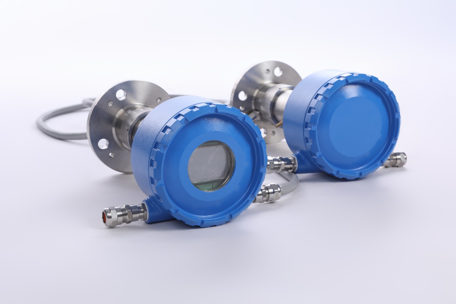


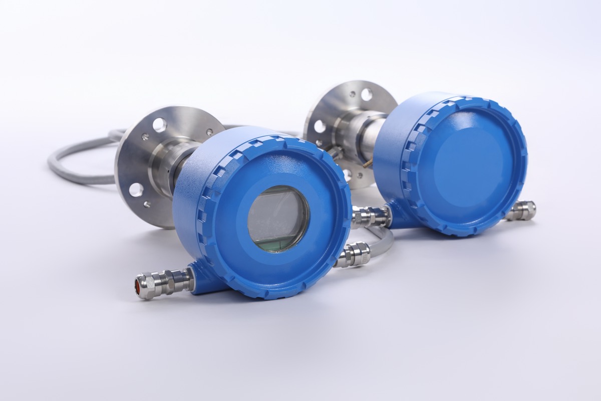
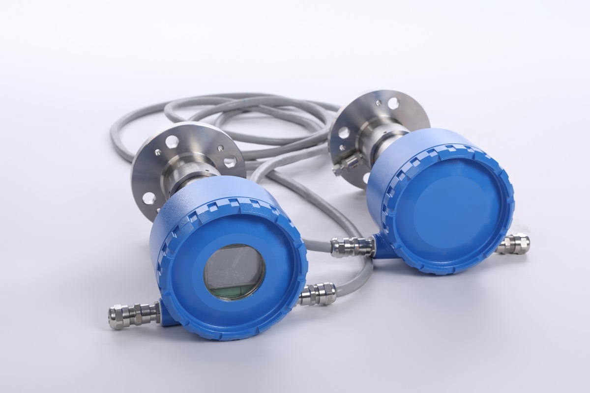
ZS8300-H2S In-Situ Explosion-Proof TDLAS H2S Analyzer
In-situ cross-stack TDLAS for H₂S in harsh, hazardous-area process gas
- Principle
- In-Situ Cross-Stack TDLAS
- Range
- Configured and confirmed at quotation
- Response
- >1 s (adjustable)
- Ex Protection
- Ex db IIC T6 Gb
Overview
The ZS8300-H2S is an in-situ, cross-stack TDLAS analyzer for H2S measurement in harsh process gas and hazardous-area duties. It uses diode-laser absorption directly across the process optical path, rather than an extractive optical-emission or reactive-tape method.
- In-situ cross-stack TDLAS
- Explosion-proof Ex db IIC T6 Gb enclosure
- SIL2-certified platform
- IP67 protection
- Designed for high-temperature, dusty and corrosive process environments
Full Technical Specifications
Key Performance
| Metric | Value | Status |
|---|---|---|
| Principle | In-Situ Cross-Stack TDLAS | confirmed |
| Range / Detection | Configured and confirmed at quotation | pending |
| Linearity Error | ≤ ±1% FS | confirmed |
| Response | >1 s (adjustable) | confirmed |
| Ex Protection | Ex db IIC T6 Gb | confirmed |
Measurement
| Specification | Value |
|---|---|
| Measuring Principle | In-Situ Cross-Stack TDLAS (diode-laser absorption) |
| Measurement Range | Configured and confirmed at quotation |
| Detection Limit | Configured and confirmed at quotation |
| Linearity Error | ≤ ±1% FS |
| Span Drift | ≤ ±1% FS |
| Optical Path Length | <5 m |
| Response Time | >1 s (adjustable) |
Physical
| Specification | Value |
|---|---|
| Installation | In-situ cross-stack (transmitter + receiver across process optical path) |
| Optical Path Length | <5 m |
| Enclosure | Explosion-proof Ex db IIC T6 Gb, IP67 |
| Dimensions / Weight | Confirmed for the installation at quotation |
Electrical
| Specification | Value |
|---|---|
| Power Supply | 24 VDC (220 VAC optional), <20 W |
| Analog Output | 2 × 4–20 mA (isolated) |
| Digital Output | Modbus RTU/TCP, HART 7 |
| Relay Outputs | 4 × SPDT |
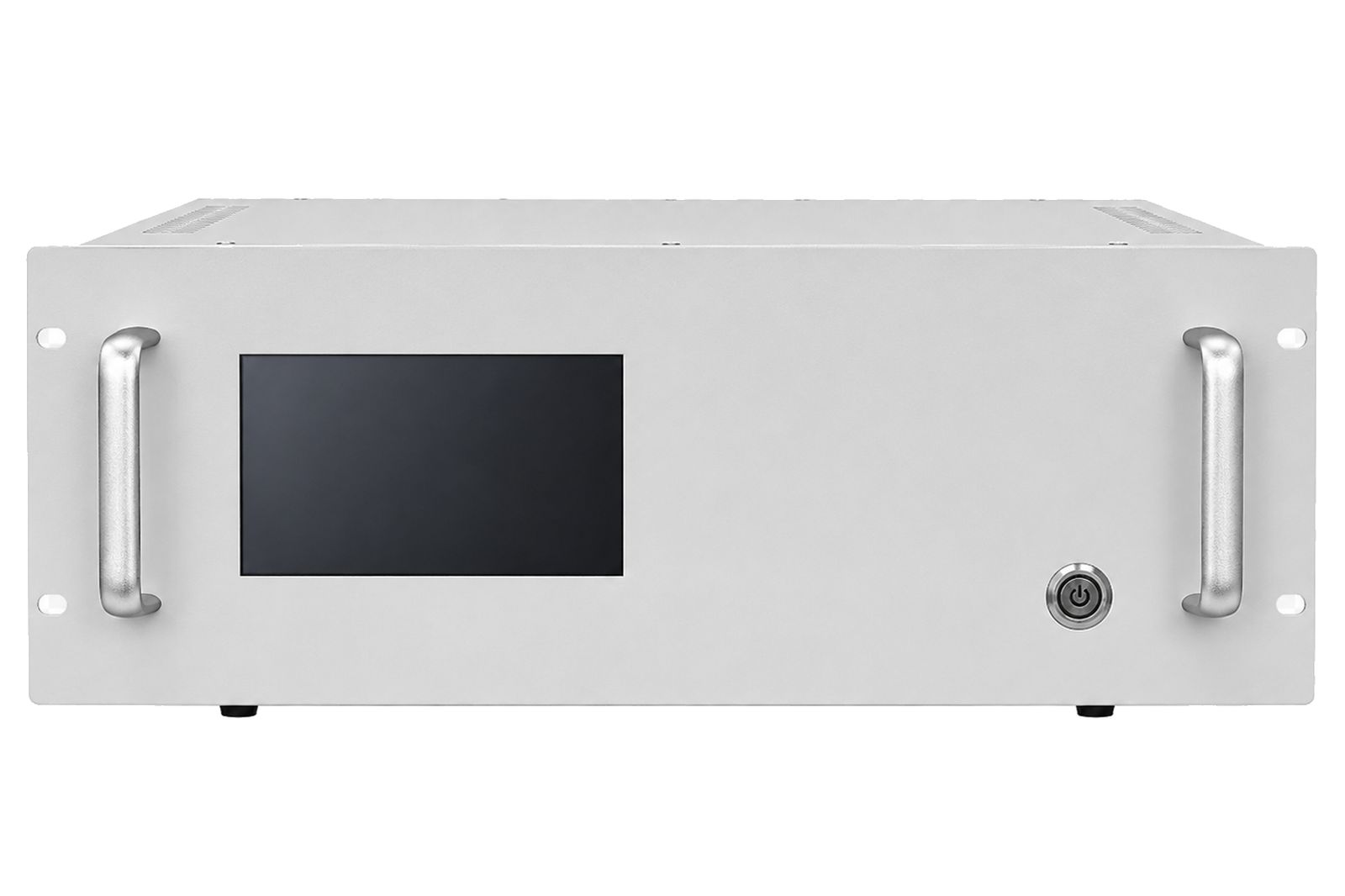
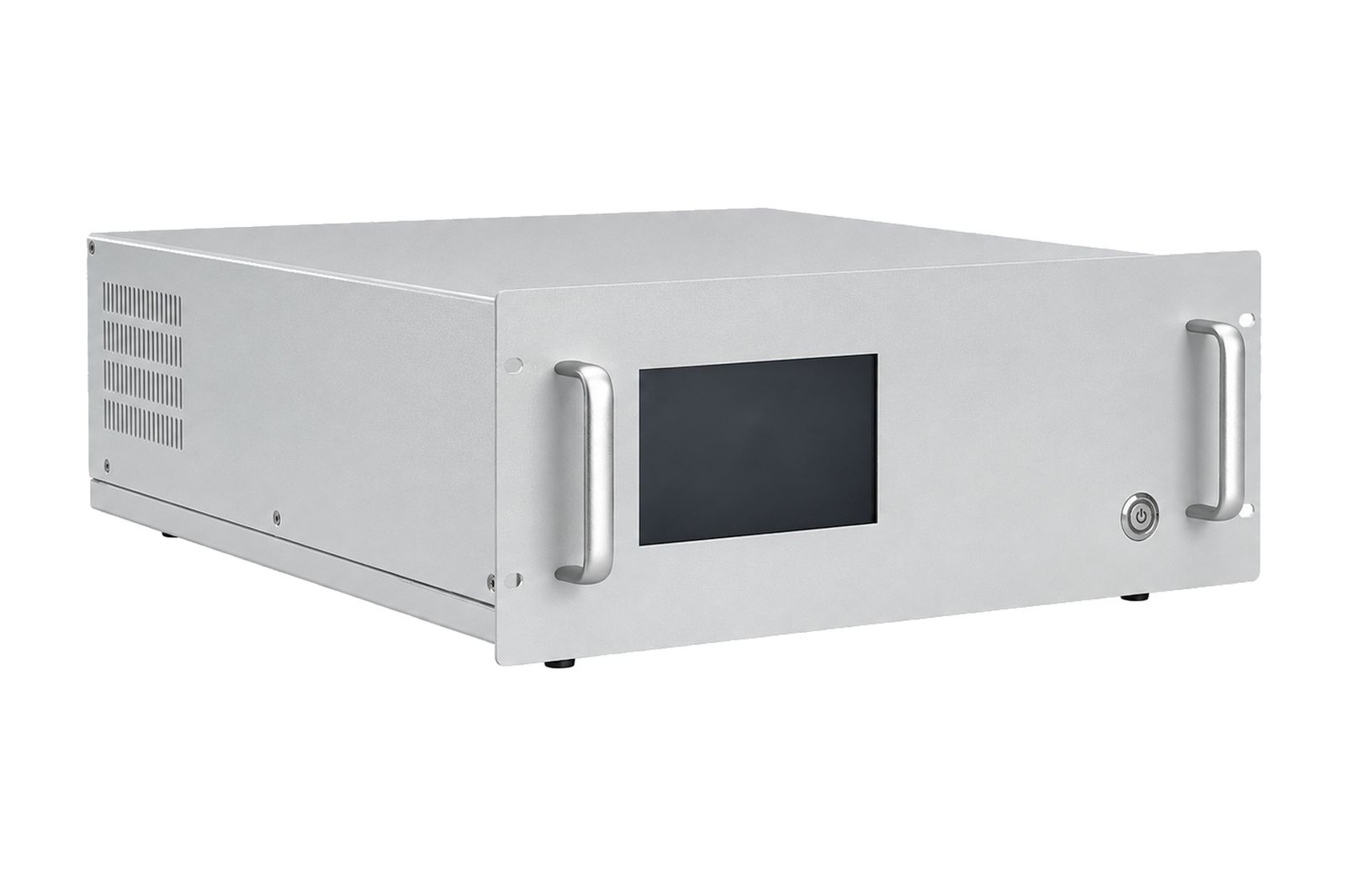
| Display | 5″ color TFT touchscreen |
Environmental
| Specification | Value |
|---|---|
| Ambient Temperature | -30 °C to +60 °C |
| Purge Gas | 0.3–0.8 MPa industrial nitrogen |
| Ingress Protection | IP67 |
| Process Environment | High-temperature, dusty and corrosive process gas |
Certifications
| Specification | Value |
|---|---|
| Explosion Protection | Ex db IIC T6 Gb |
| Design Standards | GB/T 3836.1 and GB/T 3836.2 |
| Safety Integrity | SIL2 certification |
| Ingress Protection | IP67 |
Where This Analyzer Fits
This model is mapped to the following industry applications and process duties.
Deployment Environments
Common process environments where this model is evaluated.
Certification Scope
Standards are listed with scope and status so engineering review can verify the applicable enclosure, area, and safety case.
| Standard | Scope | Variant | Status | Document |
|---|---|---|---|---|
| Ex db IIC T6 Gb | Explosion-proof hazardous-area enclosure | Standard | certified | On request |
| GB/T 3836.1 / GB/T 3836.2 | Explosion-protection design standards | Standard | certified | On request |
| SIL2 | Safety integrity level certification | Standard | certified | On request |
| IP67 | Ingress protection rating | Standard | certified | On request |
Request Documentation
Request technical datasheets, user manuals, certificates, and application notes for this model.
Evidence Notes
In-situ H₂S measurement architecture for hazardous-area process duties
Application note based on a hazardous-area process gas scenario: in-situ cross-stack TDLAS supports continuous H₂S tracking across the process optical path without an extractive sampling train. Control-loop behavior depends on optical-path alignment, purge-gas practice, and plant control setup.
Technical & Engineering Details
Secondary engineering detail — expand each topic for the full measurement, envelope, sample-system, calibration, integration, maintenance and application evidence.
01 Measurement Principle and Limits
How the measurement is bounded
In-situ cross-stack TDLAS measures H₂S continuously across the process optical path using diode-laser absorption, with no extractive sampling train.
Replaces
- Extractive sampling train across the measurement path
Requires
- 0.3–0.8 MPa industrial nitrogen purge gas
- Cross-stack optical path <5 m with aligned transmitter/receiver mounting
- Process flange access for in-situ probe installation
Interferents and Limits
- Narrow TDLAS line selection reduces cross-interference; final channel set is matrix-reviewed
- Heavy dust loading or window fouling must be managed by purge and optical-path review
02 Operating Envelope
Use these limits as selection inputs, then confirm sample condition, ambient exposure, and materials before quotation.
- Optical path beyond <5 m or with severe window fouling
- Insufficient purge-gas supply for dusty or corrosive process gas
03 Installation Boundary
Measurement mode, mounting components, and exclusions define where the analyzer responsibility ends and the process installation begins.
- cross-stack transmitter and receiver flanges
- 0.3–0.8 MPa industrial nitrogen purge supply
- optical path <5 m with alignment hardware
- Ex db IIC T6 Gb explosion-proof enclosure
- Dusty or corrosive process gas should be reviewed against purge-gas supply, window fouling, and optical-path alignment
04 Calibration & Validation
Calibration method, interval, and traceability requirements for this analyzer.
Zero / Span Method
Auto-zero and span verification with certified H₂S reference gas; intervals confirmed during commissioning
Interval
Span and auto-zero intervals set per project commissioning plan
Span Gas Traceability
Certified H₂S reference gas required
05 I/O & Integration
Signal outputs and communication interfaces for control-system integration.
Analog Output
2 × 4–20 mA (isolated)
Digital Output
Modbus RTU/TCP, HART 7
Relay Outputs
4 × SPDT
DAHS Review Note
Confirm protocol map, channel naming, alarm states, and reporting format during project integration review.
06 Maintenance & Spares site-specific
Routine service tasks, consumables, and access requirements for this analyzer; exact intervals are site-specific.
- Span verification with certified H₂S reference gas (interval per commissioning plan)
- Auto-zero review using instrument-grade N₂
- Optical window inspection and cleaning for dusty or corrosive service
- Optical-path alignment check between transmitter and receiver
- Purge nitrogen supply
- Certified H₂S reference gas
07 Application Evidence
Application context from complex industrial environments.
Application Context
Hazardous-area process gas duties with high-temperature, dusty or corrosive streams face two structural issues for H₂S monitoring: maintaining an extractive sampling train across such conditions, and keeping the analyzer inside the explosion-protection case.
Architecture Response
ZS8300-H2S with in-situ cross-stack TDLAS removes the extractive sampling train, measures H₂S directly across the process optical path, and sits inside an Ex db IIC T6 Gb explosion-proof, IP67 enclosure on a SIL2-certified platform.
Frequently Asked Questions
What advantage does in-situ TDLAS have over an extractive analyzer?
In-situ cross-stack TDLAS measures H₂S directly across the process optical path with diode-laser absorption, so there is no extractive sampling train to maintain across high-temperature, dusty or corrosive process gas.
How does it handle cross-interference in complex process gas?
Narrow TDLAS line selection reduces cross-interference; final channel set is matrix-reviewed against the specific process composition during project selection.
What is the hazardous-area certification?
The brochure-backed hazardous-area scope is Ex db IIC T6 Gb with SIL2 and GB/T 3836.1/.2 references. Non-GB hazardous-area approval requirements should be confirmed during project selection if the installation jurisdiction requires them.
What installation and purge requirements apply?
The analyzer mounts cross-stack with the transmitter and receiver across an optical path of <5 m. It uses 0.3–0.8 MPa industrial nitrogen as purge gas to keep optical windows clean in dusty or corrosive service.
What is the measurement range and detection limit?
Measurement range and detection limit are confirmed for the selected application at quotation. Linearity error and span drift are each specified at ≤ ±1% FS.
What is the expected calibration interval?
Span verification uses certified H₂S reference gas and auto-zero uses instrument-grade N₂; intervals are confirmed during commissioning for the specific installation.
Related & Alternatives
Alternative Solutions
Related Measurement Technologies
Measuring more than just h₂s? Explore complementary analytical categories.
 LEL
LEL
Combustible Gas Detectors
Fixed and portable combustible gas detection using catalytic bead and infrared sensors for explosion prevention in petrochemical, mining, and industrial environments.
View Products Multi
Multi
Multi-Gas Analyzers
Simultaneous multi-component gas analysis using multi-pass TDLAS, NDIR, and combined-sensor platforms for complex process streams, comprehensive CEMS, and research applications.
View ProductsCompare ZS8300-H2S with adjacent options
Review neighboring models by technology, range, accuracy basis, and form factor before moving to quotation.
When this model is preferred
Select ZS8300-H2S when its measurement principle, range, and form factor match the process duty and certification scope.
When to consider an alternative technology
Consider another analyzer when the gas matrix, sample temperature, hazardous-area scope, or reporting requirement falls outside the stated envelope.
Review ZS8300-H2S against site conditions
Send gas range, sample temperature, pressure, moisture, and certification needs before final model selection.