
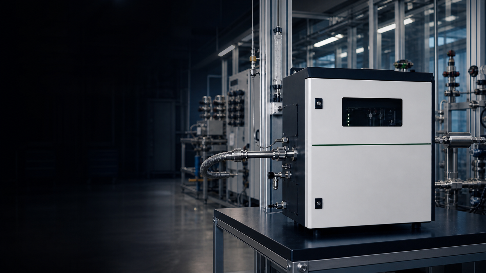
CLD Gas Analyzers — Chemiluminescence Detection for NO / NO₂ / NOₓ
Gas-phase NO + O₃ photon chemistry: the reference-method standard for stationary-source NOₓ under EPA Method 7E and EN 14792, ambient NO₂ monitoring under 40 CFR Part 50 Appendix F, and SCR / SNCR closed-loop feedback.
What Is CLD Gas Analysis?
Chemiluminescence detection (CLD) is a gas-phase chemical reaction method — not a spectroscopic technique. NO in the sample stream reacts with ozone (O₃) generated on-board, producing excited nitrogen dioxide molecules (NO₂*) that emit photons across a 600–3000 nm band. A red-sensitive photomultiplier tube (PMT) counts those photons; the count rate is linear with NO concentration across several concentration decades. Because the reaction is highly specific to NO + O₃, CLD achieves low cross-interference from CO₂, H₂O, SO₂, or CO — the matrix gases that challenge broadband NDIR in the same spectral region. NO₂ cannot react directly with O₃, so it is measured indirectly: a heated converter (molybdenum catalyst at ~350 °C for stack duty, or a photolytic UV-LED converter for ambient compound-clean monitoring) reduces NO₂ → NO upstream of the reaction cell. NOₓ = NOₓ_total − NOₓ_bypass (converter bypassed). This converter + PMT architecture is why CLD instruments carry more OPEX than optical analyzers, and why the technology is specifically suited to NOx reference-method duty rather than wide multi-gas coverage.
CLD Measurement Principle
Engineering & OPEX Notes
- The O₃ generator (corona-discharge cell) has a finite service life and must be replaced on schedule — typically every 1–3 years depending on duty; budget for it explicitly in the project OPEX forecast.
- Molybdenum converter cartridges at ~350 °C require periodic replacement (2–4 years typical) and can interfere on HNO₃, PAN, and alkyl nitrates in ambient matrices — specify photolytic converter for compound-specific ambient NOx work.
- The integral vacuum pump maintains reaction-cell pressure — a consumable requiring periodic rebuild. Include pump kit in the site spares list at commissioning.
- NO calibration span cylinders (certified NO in N₂ balance) are mandatory for EPA Method 7E and EN 14792 CEMS compliance; coordinate with the site gas-cylinder management programme.
- CLD measures NO and NOₓ only — it does not simultaneously report SO₂, CO, CO₂, or NH₃. Multi-parameter CEMS stacks typically pair CLD (NOx) with UV-DOAS (SO₂, NH₃) or NDIR (CO, CO₂) on a common data logger.
- Quenching species (CO₂, H₂O, halogens at elevated partial pressures) can suppress the photon yield and bias readings low; for wet-stack or high-CO₂ matrices, quench correction or dry-extract sampling is required.
NO / NO₂ / NOₓ — How CLD Actually Measures Them
The CLD reaction responds only to NO. NO₂ is measured indirectly by converting NO₂ → NO first, then reacting with O₃; NOₓ is the sum. The three-way chain defines why CLD instruments always ship with a converter module, and why ambient compound-clean NO₂ monitoring uses a photolytic converter rather than molybdenum.
NO (Nitric Oxide)
Reacts directly with O₃ in the reaction cell, emitting photons at 600–3000 nm, counted by the PMT. Linear response across several concentration decades; no converter needed. CLD’s native and most accurate measurement.
NO₂ (Nitrogen Dioxide)
Molybdenum catalyst at ~350 °C (stack default) or photolytic UV-LED converter (ambient compound-clean) reduces NO₂ → NO upstream of the reaction cell. NO₂ = NOₓ − NO. Converter efficiency and specificity are the critical uncertainty terms.
NOₓ (Total NO + NO₂)
The analyzer cycles between converter-inline (total NOₓ) and converter-bypass (native NO) modes. NOₓ is the quantity scored by EPA Method 7E (40 CFR Part 60) and EU EN 14792 on regulatory stacks. Typical cycle time 10–30 s.
| Dimension | NO | NO₂ | NOₓ (Total) |
|---|---|---|---|
| Reaction path | Direct: NO + O₃ → NO₂* + O₂, then NO₂* → NO₂ + hν | Indirect: converter NO₂ → NO, then same reaction | Converter inline: sum of converted NO₂ + native NO together |
| Converter needed | No | Yes — Mo (~350 °C) or photolytic UV-LED | Yes (to capture NO₂ component) |
| Typical range (stack) | 0–500 ppm (configurable) | Derived: NOₓ − NO | 0–500 ppm (configurable, EPA Method 7E context) |
| Typical range (ambient) | Sub-ppb to tens of ppb | Sub-ppb to tens of ppb (photolytic converter) | Sub-ppb to hundreds of ppb (40 CFR Part 50 App F) |
| Converter specificity | N/A | Mo: responds to HNO₃, PAN, alkyl nitrates too (overestimate). Photolytic: specific to NO₂ only. | Determined by converter type; Mo converter bias propagates into NOₓ |
| Regulatory basis | Reported separately in some ambient networks | Derived channel; 40 CFR Part 50 App F ambient | EPA Method 7E (stationary CEMS); EN 14792 (EU); 40 CFR Part 50 App F (ambient) |
| Key uncertainty | PMT linearity at high NO; quench by CO₂ / H₂O at elevated partial pressures | Converter efficiency (degradation over time); Mo cross-response to organic nitrates | Sum of NO and converter uncertainties; response-time difference between bypass and inline cycles |
Gas Coverage & Category Links
CLD is specific to NO / NO₂ / NOₓ chemistry. For SO₂, NH₃, CO, CO₂, or multi-parameter CEMS requirements, see the related-products and comparison modules below.
CLD vs UV-DOAS / TDLAS / NDIR / FTIR
CLD is the chemistry-specific reference-method outlier in a room full of optical techniques. Pick the technology that matches the physics, the matrix, and the regulatory framework — on most modern CEMS racks CLD and UV-DOAS run on the same stack because they are good at different things.
| Parameter | CLD | UV-DOAS | TDLAS | NDIR | FTIR |
|---|---|---|---|---|---|
| Detection principle | Gas-phase NO + O₃ chemiluminescence; PMT photon count | UV differential optical absorption (190–400 nm) | Near/mid-IR single-line laser absorption | Mid-IR broadband filtered absorption | Mid-IR full-spectrum Fourier-transform IR |
| Target gases | NO, NO₂ (indirect), NOₓ only | SO₂, NO₂, NH₃, Cl₂, O₃, HCl, and others simultaneously | One gas per laser module (NH₃, HF, HCl, CO, H₂S, O₂, etc.) | CO, CO₂, CH₄, N₂O, hydrocarbons (1–5 channels) | 10+ gases simultaneously by full-spectrum deconvolution |
| Multi-gas simultaneous | No — NOx only; must be paired with other technology for SO₂ / CO / CO₂ | Yes — single optical head covers multiple UV-absorbing species | Conditional: multi-laser configurations add species but increase cost | Limited (3–5 channels max) | Yes — strongest multi-species option in IR region |
| Detection range | Sub-ppb (ambient) to low-ppm (stack CEMS) | ppm range for most UV-absorbing species; sub-ppm for long-path open-path systems | Sub-ppm to ppb on favorable absorption lines | ppm to %vol depending on path length and gas species | ppm to sub-ppm, species-dependent |
| Cross-interference | Low for NO directly; CO₂ / H₂O quench chemiluminescence at high partial pressures. Mo converter overestimates by reacting with organic nitrates and HNO₃ | Low in UV band; matrix must have UV-absorbing target gas | Excellent single-line selectivity; collision broadening by matrix species can bias results in complex matrices | H₂O continuum and overlapping IR bands are the main risks | Excellent — full spectral deconvolution resolves overlaps |
| Reference-method status | EPA Method 7E (40 CFR Part 60) / EN 14792 (EU) for stationary NOx CEMS; 40 CFR Part 50 App F for ambient | EN 14211 (NO₂) / EN 14212 (SO₂) reference-equivalent in EU; EPA PS-18 Conditional for some UV systems | Accepted in some MCERTS / EPA PS applications; confirm with local regulator | Method 10 (CO) / Method 3A (CO₂ / O₂) — widely accepted | EN 14181 QAL1 approved for some EU IED multi-gas CEMS duties |
| OPEX profile | Higher: O₃ generator, Mo converter cartridge, vacuum pump, NO span cylinder | Low to moderate: optical alignment, UV source lamp (long-life) | Low: laser module is long-lived; no consumable chemistry | Low: optical windows; no consumable chemistry | Moderate: detector cryocooling or room-temperature version; IR source |
| Typical response (T90) | 10–60 s (including converter cycle time) | 10–30 s | <2–10 s | 15–60 s | 30–120 s (FTIR scan averaging) |
Choose CLD When…
- EPA Method 7E / EN 14792 stationary-source NOₓ reference-method defensibility is the scoring criterion
- Ambient NO / NO₂ reporting under 40 CFR Part 50 Appendix F at sub-ppb concentration levels
- Matrix-interference immunity from SO₂ / CO₂ / H₂O / CO at stack concentrations is a hard requirement
- Engine or automotive laboratory transient NOₓ measurement on a multi-decade dynamic range
- SCR / SNCR closed-loop NOₓ feedback where long-term drift-stable reporting is the control variable
Route to UV-DOAS / TDLAS / NDIR / FTIR When…
- Multi-gas simultaneous output (SO₂ + NO₂ + NH₃ + Cl₂) is the project need — UV-DOAS
- Single-line sub-ppm selectivity in a corrosive or complex matrix (NH₃, HF, HCl) — TDLAS
- CO / CO₂ CEMS or combustion and IAQ duty — plain or GFC NDIR
- Lab speciation across 10+ unknown species — FTIR full-spectrum deconvolution
- Duty cannot tolerate O₃ generator + Mo converter + vacuum pump OPEX — choose an optical path
CLD in NOₓ Duty
From stationary-source CEMS under EPA Method 7E and ambient air quality networks to SCR feedback and engine-lab transient testing — where CLD earns its place and where OPEX is justified by the regulatory requirement.
EPA Method 7E Stationary-Source CEMS
- Challenge
- Power plants, cement kilns, waste incinerators, and industrial boilers regulated under 40 CFR Part 60 / Part 75 require continuous NOₓ reporting with reference-method defensibility. Regulatory auditors expect Method 7E traceability and QA Level RATA compliance — optical proxies may not satisfy the permit condition.
- Solution
- CLD extractive CEMS on a heated sample line with Mo converter for stack-range NOₓ. Paired with a UV-DOAS or NDIR head for SO₂ and CO on the same data logger. ZS-CEMS-200 family supports combined CLD + UV-DOAS rack integration.
Ambient NO / NO₂ Monitoring (40 CFR Part 50)
- Challenge
- Urban air quality networks and near-source impact studies require sub-ppb NO and NO₂ measurement for NAAQS compliance and health-impact reporting. Molybdenum converters in ambient applications over-estimate NO₂ by responding to HNO₃ and PAN, biasing regulatory data.
- Solution
- CLD with a photolytic UV-LED converter for compound-specific NO₂ detection under 40 CFR Part 50 Appendix F reference-equivalent status. Photolytic converter eliminates the Mo interference bias at ambient concentrations.
SCR / SNCR NOₓ Closed-Loop Feedback
- Challenge
- Selective catalytic (SCR) and non-catalytic (SNCR) reduction systems for power stations and large combustion plants need a drift-stable NOₓ signal at the SCR inlet and outlet to optimise reagent (urea / ammonia) dosing and minimise reagent slip, with measurement reliability compatible with 24/7 closed-loop control.
- Solution
- Dual-point CLD (pre-SCR + post-SCR) provides a stable NOₓ differential for reagent control logic. The chemistry-specific response avoids optical drift artefacts from flyash and window contamination. Post-SCR measurement also captures residual NO for combined NH₃ slip estimation when paired with TDLAS.
Engine & Automotive Laboratory
- Challenge
- Heavy-duty engine certification, automotive transient-cycle testing (WLTP, FTP, RDE), and marine Tier II / III compliance require fast-response, high-dynamic-range NOₓ measurement in raw exhaust at concentrations ranging from single-ppm to thousands of ppm within the same test cycle.
- Solution
- CLD is the accepted reference instrument in engine-test-cell emission measurement systems (EMS / CVS dilution tunnel). Multi-decade linear range, fast response, and protocol acceptance under ISO 8178, ECE R49, and EPA CFR Part 1065 make it the default in this sector.
Combustion Optimisation & Boiler Tuning
- Challenge
- Industrial boilers, gas turbines, and fired heaters operating near NOx permit limits need real-time NOₓ feedback to optimise combustion staging, excess-air ratio, and burner sequencing without exceeding the permit ceiling or sacrificing thermal efficiency.
- Solution
- CLD (for NOₓ) combined with NDIR (CO / CO₂) provides a complete combustion-efficiency and emission-management loop. The chemistry-specific NOₓ signal is insensitive to CO₂ and H₂O in the flue gas, avoiding the cross-interference that can mislead broadband optical systems on wet flue gas.
GESHINE CLD / NOₓ Family
Cross-links to real GESHINE NOₓ-capable products, the SO₂ / NOₓ category, and the companion UV-DOAS technology. Electrochemical NOₓ sensing is intentionally absent here — it belongs to the SO₂ / NOₓ category page but is not CLD chemistry.
ZS-CEMS-200 SO₂ / NOₓ CEMS Package
Integrated CEMS package combining UV-DOAS for SO₂ and Chemiluminescence detection for NOₓ on a single extractive rack. Targets 40 CFR Part 60 / EU IED BAT stack-gas compliance with combined SO₂ + NOₓ reporting from one system.
View ProductZS6200-SO₂ / ZS6100-NOₓ Analyzer Platform
SO₂ / NOₓ analyzer platform pairing the ZS6200-SO₂ UV-fluorescence analyzer with the ZS6100-NOₓ chemiluminescence (CLD) analyzer for stack-range ppm monitoring. Combined dual-channel output for SO₂ and NOₓ reporting.
View ProductSO₂ / NOₓ Analyzer Category
Full SO₂ / NOx family — including the CLD-based ZS-CEMS-200, the ZS6200-SO₂ / ZS6100-NOₓ UV-fluorescence and CLD platform, and electrochemical NOₓ options — with cross-technology selection guidance for stack CEMS and process NOx applications.
Browse CategoryMulti-Gas Analyzer Category
For projects needing NOₓ alongside SO₂, CO, CO₂, and O₂ on a single platform — multi-technology CEMS suites where CLD (for NOx) pairs with UV-DOAS and NDIR channels on a common sample handling system.
Browse CategoryCLD Gas Analyzer FAQ
Common questions on when to choose CLD over UV-DOAS, why NO₂ is measured indirectly, converter technology selection, real OPEX, and how EPA Method 7E relates to 40 CFR Part 50 ambient monitoring.
What is a CLD gas analyzer?
A CLD (Chemiluminescence Detection) gas analyzer measures NO concentration by exploiting the gas-phase reaction between nitric oxide (NO) and ozone (O₃) generated inside the instrument. The reaction produces electronically excited nitrogen dioxide molecules (NO₂*) that emit photons in the 600–3000 nm band; a red-sensitive photomultiplier tube (PMT) counts those photons. The photon-count rate is linear with NO concentration over several decades, giving CLD both high sensitivity (sub-ppb for ambient duty) and wide dynamic range (ppm-scale for stack CEMS).
CLD is a chemical reaction instrument, not a spectroscopic technique — it does not rely on light absorption by the target gas. This is why CLD is largely immune to infrared or UV cross-interference from CO₂, H₂O, SO₂, and CO that affect NDIR and UV-DOAS in the same application environments.
Why is NO₂ measured indirectly in a CLD analyzer?
The CLD reaction is specific to NO: NO₂ does not react with O₃ in a way that produces a detectable photon yield. To measure NO₂, a converter upstream of the reaction cell first reduces NO₂ to NO. The instrument then reports total NOₓ with the converter in-line, and native NO with the converter bypassed; NO₂ is calculated by subtraction: NO₂ = NOₓ − NO.
The choice of converter technology matters. A molybdenum catalyst at ~350 °C (the standard for stack CEMS) converts NO₂ efficiently but also reduces organic nitrates, HNO₃, and PAN to NO, which over-estimates NO₂ in atmospheric measurement. A photolytic UV-LED converter dissociates NO₂ specifically without affecting these interfering nitrogen compounds, and is the preferred choice for ambient air quality networks under 40 CFR Part 50 Appendix F.
What is the difference between CLD and UV-DOAS for NOx measurement?
CLD and UV-DOAS measure NOₓ by different physical principles and serve different regulatory roles. CLD uses the NO + O₃ gas-phase reaction and is accepted as a reference method under EPA Method 7E (40 CFR Part 60 Appendix A) and EU EN 14792 for stationary-source CEMS. It is highly selective to NO chemistry and immune to infrared-region spectral interferences.
UV-DOAS uses differential optical absorption spectroscopy in the UV range (190–400 nm) and measures NO₂ directly by its UV absorption — but it also covers SO₂, NH₃, O₃, and Cl₂ simultaneously from one optical head. On a modern CEMS rack, CLD and UV-DOAS are often installed together: CLD handles NOₓ reporting (for Method 7E defensibility) while UV-DOAS handles SO₂ and the other multi-gas components. Neither technology makes the other redundant — they are complementary.
What are the main OPEX items on a CLD analyzer?
CLD carries higher OPEX than optical analyzers because it depends on consumable chemistry components. The four main OPEX items are: (1) the O₃ generator (corona-discharge cell), which degrades over 1–3 years of service and must be replaced; (2) the converter cartridge — molybdenum catalyst at ~350 °C for stack duty, with a typical service life of 2–4 years; (3) the integral vacuum pump, which maintains reaction-cell pressure and requires periodic rebuild or replacement; and (4) certified NO-in-N₂ span gas cylinders for calibration validation, mandated by EPA Method 7E QAL and RATA protocols.
These consumables should be explicitly costed in the project OPEX forecast and included in the site-maintenance schedule. CLD’s regulatory reference-method status justifies this cost structure for applications where EPA Method 7E or EN 14792 compliance is the design requirement; for non-regulatory NOx indication where OPEX is the ranking criterion, an optical technology may be more appropriate.
What is EPA Method 7E, and how does it differ from 40 CFR Part 50 Appendix F?
EPA Method 7E (40 CFR Part 60 Appendix A) is the reference method for measuring nitrogen oxides from stationary sources — power plants, industrial boilers, cement kilns, and other large combustion sources subject to New Source Performance Standards (NSPS) or Title V permit limits. Method 7E specifies CLD as the approved instrumental technique and defines sampling, calibration, quality assurance, and data reporting requirements for stack CEMS. Results are in ppm (dry basis) and feed into annual compliance reports to state and federal regulators.
40 CFR Part 50 Appendix F is an ambient monitoring reference for NOx at ground-level air quality stations under the National Ambient Air Quality Standards (NAAQS). This context deals with sub-ppb concentrations at population exposure locations — not stack plumes. The instrument requirements and converter specifications differ (photolytic converters are favoured here to avoid Mo over-estimation of NO₂), and the regulatory framework (NAAQS attainment, AQS data) is separate from the industrial CEMS world. A single CLD instrument can be configured for either duty, but the converter technology, concentration ranges, and QA requirements differ significantly between the two.
Can CO₂ or water vapour interfere with CLD measurement?
CLD is largely immune to the spectral cross-interferences (infrared and UV absorption overlap) that affect NDIR and UV-DOAS. However, high partial pressures of CO₂, H₂O, and certain halogens can quench the CLD photon yield — the excited NO₂* molecules collide with these quenching species before emitting a photon, causing the PMT count to be lower than the true NO concentration. This is known as chemiluminescence quenching.
In most industrial stack CEMS applications (flue gas at typical CO₂ concentrations of 5–15%), quenching effects are modest and can be corrected by applying matrix-specific quench correction coefficients derived from calibration. For wet-stack sampling or high-CO₂ matrices (e.g. post-combustion capture stacks), quench correction or dry-extract sampling is recommended to maintain measurement accuracy. The application engineer should be given the expected background CO₂ and H₂O composition range at the measurement point so appropriate correction can be built into the analyser configuration.
What information do I need to provide for a CLD analyzer quotation?
To configure the right CLD solution our application engineers typically need: the measurement duty (EPA Method 7E stack CEMS / 40 CFR Part 50 ambient / engine-lab / SCR feedback control), the target species (NO only, NO + NO₂ via converter, total NOₓ), the required concentration range and detection limit (sub-ppb ambient versus ppm-range stack), and whether a molybdenum or photolytic converter is appropriate for the matrix.
Additional details that refine the scope include: the background gas matrix composition (dry stack, wet FGD outlet, raw diesel exhaust, urban ambient), the regulatory framework (EPA Part 60 / Part 75 / Part 50, EU IED BAT, EN 14792, Tier 4 / Euro 6 engine standards), site OPEX tolerance for O₃ generator, vacuum pump, and Mo converter consumables, and the preferred output protocols (4–20 mA, RS-485 Modbus, HART). With this information the team can confirm whether CLD alone is the right answer, or whether a combined CLD + UV-DOAS rack is more appropriate for the full parameter set.
Request a Quote for CLD Gas Analyzers
To configure the right CLD analyzer for your NOₓ duty, please have these details ready:
- Duty: EPA Method 7E stack CEMS / 40 CFR Part 50 Appendix F ambient / engine-lab / SCR feedback
- Target species: NO only / NO + NO₂ via converter / total NOₓ
- Required range and detection limit (sub-ppb ambient vs ppm stack)
- Converter type: molybdenum at 350 °C (stack) or photolytic UV-LED (ambient)
- Matrix composition: dry stack, wet-FGD outlet, raw diesel exhaust, ambient urban
- Regulatory framework: EPA Part 60 / Part 75 / Part 50, EU IED BAT, EN 14792, Tier 4 / Euro 6
- OPEX tolerance: O₃ generator corona cell, vacuum pump, Mo converter cartridge, NO span cylinder
- Output protocols (4–20 mA / RS-485 Modbus / HART) and CEMS data-logger hookup

Get CLD Expert Consultation
Our application engineers will confirm whether CLD is the right NOₓ answer for your duty, or whether the project should pair CLD with UV-DOAS on a combined CEMS rack — and then scope the right converter and reaction-cell configuration.