
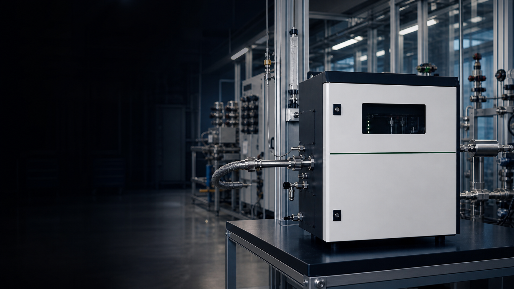
UVF Gas Analyzers — Ultra-Violet Fluorescence for SO₂ Measurement
Pulsed UV Fluorescence (UVF) is the SO₂-first reference-method chemistry behind EPA Method 6C stationary CEMS, 40 CFR Part 50 Appendix A ambient monitoring, FGD outlet, and Claus tail-gas SO₂ duty where defensibility matters.
UVF measures emitted light, not transmitted light: a pulsed ≈214 nm UV source excites SO₂ molecules; the excited SO₂* relaxes by fluorescing at 240–410 nm (peak ≈350 nm); a photomultiplier tube counts the emitted photons. That fluorescence-emission physics is what gives UVF its sub-ppb ambient sensitivity and regulatory reference-method status — and it is single-component SO₂ only, not a multi-gas platform.
What Is UV Fluorescence?
UVF is not a spectroscopy method in the absorption sense — it is a fluorescence-emission method. A pulsed UV source at ≈214 nm excites SO₂ molecules to an electronically excited state; the excited SO₂* relaxes by emitting a fluorescence photon in the 240–410 nm band (broad, peak near 350 nm) which a photomultiplier tube (PMT) counts. The instrument therefore measures emitted light, not transmitted light, which gives UVF an excellent signal-to-noise ratio at sub-ppb ambient concentrations and the regulatory-reference status that EPA Method 6C and 40 CFR Part 50 Appendix A document. What UVF is not: it is not a multi-gas simultaneous method (that is UV-DOAS or FTIR), it is not a UV absorption method (that is UV-DOAS, with completely different optics), and it is not free of consumables — the UV lamp ages on a 5000–8000 hour schedule, and aromatic-hydrocarbon scrubbers are mandatory on petrochemical / Claus duty because aromatic HC quench the fluorescence and cause negative SO₂ bias.
UVF Measurement Principle
Engineering & Operating-Cost Notes
- UVF is fluorescence emission — the PMT measures emitted light, not transmitted light. This gives an excellent SNR at low concentrations because the dark photon count (not source-fluctuation noise) limits detection.
- Aromatic hydrocarbons (benzene, toluene, naphthalene) absorb at 214 nm and quench excited SO₂* via collisional energy transfer, producing a negative SO₂ bias. A hydrocarbon scrubber upstream of the reaction cell is mandatory — not optional — on petrochemical / refinery / Claus tail-gas matrices.
- UV lamp aging is the dominant long-term drift source: pulsed Zn / Cd hollow-cathode lamps run 5000–8000 hours; UV LED designs extend this to 20,000+ hours but introduce different drift characteristics. Planned lamp-replacement schedules must be in the maintenance contract.
- Sample conditioning: the cell must be kept dry (water vapor scatters UV at 214 nm and adds noise), optics must be clean (UV degrades organic films into absorbing residues), and a particulate filter upstream prevents fouling.
- The operating-cost budget is real: UV lamp (5000–8000 h), hydrocarbon scrubber cartridge (3–12 month life depending on aromatic loading), PMT (5–10 year drift), traceable SO₂-in-N₂ span cylinders on a 30–90 day interval. UVF is not a no-consumable method.
- UVF is single-channel (SO₂ only) — it does not give simultaneous NOₓ / Cl₂ / NH₃ output. Multi-gas stacks pair UVF SO₂ with CLD NOₓ (e.g. a ZS6200-SO2 / ZS6100-NOx platform) or with UV-DOAS multi-gas; UVF is not the multi-gas head.
SO₂ Measurement — The UVF Reference-Method Recipe
UVF is a SO₂-first single-component technology. The eight-step specification checklist below is what an operator runs from source selection through regulatory reference method — miss any step on petrochemical or Claus duty and the SO₂ number stops being defensible.
- 1Excitation Wavelength
- ≈214 nm pulsed UV source (Zn / Cd hollow-cathode lamp historically; UV LED in modern designs). Matches the SO₂ B³B₁ ← X¹A₁ electronic absorption.
- 2Fluorescence Emission Band
- 240–410 nm broad band, peak near 350 nm. The Stokes shift between excitation (214 nm) and emission (350 nm) optically isolates the detector from the source.
- 3Detector Geometry
- PMT positioned at 90° to the excitation beam axis; bandpass filter (300–400 nm) isolates fluorescence from scattered UV; phase-locked demodulation against source pulses rejects ambient stray light.
- 4Typical Dynamic Range
- Sub-ppb (ambient EPA reference) to 0–1000 ppm (CEMS / Claus tail-gas) on a single instrument range profile.
- 5Sample Conditioning
- Heated sample line (above SO₂ dew point), particulate filter, dryer (or low-pressure cell to reduce H₂O scattering), and — critically — hydrocarbon scrubber upstream of the reaction cell on any matrix carrying aromatic HC.
- 6Span / Calibration
- Traceable SO₂-in-N₂ cylinders on a 30–90 day interval per regulatory program; zero check on scrubbed-zero air; periodic span validation against permeation-tube SO₂ standards.
- 7Cross-Interference
- Aromatic HC quenching is the dominant interferent (negative SO₂ bias). H₂S, NO, NO₂ do not significantly interfere with UVF SO₂ at the target wavelengths once the hydrocarbon scrubber is in place.
- 8Regulatory Reference Method
- US EPA Method 6C (stationary-source instrumental SO₂ CEMS); 40 CFR Part 50 Appendix A (ambient SO₂ UVF reference); EN 14791 (EU stationary-source SO₂ reference is wet-chemistry, but UVF instruments are widely accepted as continuous reference instruments under MCERTS / EN 15267 type-approval frameworks).
UVF vs UV-DOAS / CLD / NDIR / TDLAS
UVF shares the ultraviolet wavelength range with UV-DOAS but is fundamentally different physics — fluorescence emission rather than differential absorption. On the full peer landscape UVF is the SO₂-only reference-grade outlier; pick the technology that matches the physics, the matrix, and the regulatory framework.
| Parameter | UVF | UV-DOAS | CLD | NDIR | TDLAS |
|---|---|---|---|---|---|
| Physics | Pulsed UV at 214 nm excites SO₂; SO₂* fluoresces at 240–410 nm; PMT counts emitted photons (fluorescence emission) | UV broadband source; differential absorption 190–400 nm; CCD spectrometer | Gas-phase chemistry NO + O₃ → NO₂* → photon (chemistry, not optics) | Mid-IR broadband absorption through filter | Single-mode laser absorption, near-IR |
| Target Species | SO₂ only (UVF physics also applies to H₂S separately) | SO₂ / NO₂ / Cl₂ / NH₃ / O₃ multi-gas | NO / NO₂ / NOₓ only | CO / CO₂ / CH₄ / refrigerants | One gas per laser head |
| Typical Detection Limit | Sub-ppb (ambient reference); ppm to low-ppm on stack / CEMS | Low-ppm extractive; sub-ppm to low-ppb on long-path | Sub-ppb (ambient); ppm to low-ppm stack | ppm (low-range 0.5–5 ppm clean matrix) | Sub-ppm to ppb on favorable lines |
| Response Time (T90) | <30 s (process); <80 s (ambient with conditioning) | 10–30 s typical | <20 s (plus O₃ generator warm-up) | 15–60 s typical | <1–10 s |
| Multi-Gas Simultaneous | No — SO₂ only | Yes — SO₂ / NO₂ / NH₃ / Cl₂ / O₃ on one head | No — NOₓ only | Yes via filter wheel (3–5 channels) | One gas per laser; multi-gas = multi-laser |
| Key Interference | Aromatic hydrocarbons quench SO₂* → negative bias; pre-cutter mandatory on petrochemical duty | Differential fit rejects broadband attenuation; water-vapor immune | Mo converter ages and reduces NH₃ / HNO₃ partially | H₂O continuum and overlapping IR bands | Resolved by laser-line selection |
| Consumables / Running Cost | UV lamp 5000–8000 h + HC scrubber 3–12 month + PMT + span cylinders | UV source lamp aging (D₂ 1000–2000 h; Xe 2000–5000 h) | O₃ generator + Mo converter + vacuum pump + PMT + span gas | IR source lamp + span gas; dryer if deployed | Essentially none (laser diode 10+ year life) |
| Regulatory Reference Method | US EPA Method 6C (stationary SO₂); 40 CFR Part 50 App A (ambient SO₂ UVF reference) | EN 14791 (SO₂), EN ISO 21877 (NH₃), EN 14793 (NO₂ backup) | US EPA Method 7E (stationary NOₓ); 40 CFR Part 50 App F (ambient NOₓ) | US EPA PS-3 / PS-4 (CO, CO₂) | Project-specific reference method alignment |
| Best For | SO₂-only reference-grade CEMS, FGD outlet, Claus tail-gas, ambient SO₂ | Multi-gas CEMS (SO₂ / NO₂ / NH₃ / Cl₂), wet stack, long-path ambient | Regulatory NOₓ CEMS, ambient air-quality NOₓ, engine exhaust labs | CO / CO₂ CEMS, combustion control, IAQ | Low-ppm / corrosive / complex matrix, single-gas selectivity |
Choose UVF When…
- Target is SO₂ only, with reference-method defensibility as the scoring criterion (EPA Method 6C stationary or 40 CFR Part 50 Appendix A ambient)
- Sub-ppb ambient SO₂ reporting at regulatory air-quality stations
- FGD outlet SO₂ where fast, drift-stable single-component reading is the deliverable
- Claus tail-gas SO₂ where the matrix allows a proper upstream hydrocarbon scrubber
- Project accepts UV-lamp lifecycle and HC-scrubber cartridge running cost as part of the total cost
Route to UV-DOAS / CLD / NDIR / TDLAS When…
- Multi-gas simultaneous output (SO₂ + NO₂ + NH₃ + Cl₂) is the project need — UV-DOAS
- Regulatory NOₓ reference method (EPA Method 7E / 40 CFR Part 50 App F) — CLD
- CO / CO₂ CEMS, combustion control, or IAQ — NDIR
- Single-line sub-ppm selectivity in corrosive / hot-wet matrix — TDLAS
- Matrix carries untreatable aromatic hydrocarbons (quenching cannot be scrubbed out) — UV-DOAS differential fit
UVF in SO₂ Duty
From EPA Method 6C stationary CEMS and FGD outlet monitoring to Claus tail-gas and ambient air-quality SO₂ — where UVF earns its reference-method status in real industrial and regulatory duty.
EPA Method 6C Stack SO₂ CEMS
- Challenge
- Stationary-source SO₂ reporting under 40 CFR Part 60 / Part 75 and EU IED BAT requires an instrumental method that survives RATA against the reference and holds long-interval span discipline. UV-DOAS handles wet-stack multi-gas, but for SO₂-only duty the regulatory pedigree of UVF is hard to displace.
- Solution
- UVF SO₂ with hydrocarbon scrubber and heated sample line is the Method 6C instrumental reference path. The ZS6200-SO2 / ZS6100-NOx platform pairs UVF SO₂ with chemiluminescence NOₓ in one rack-mount platform. Method 6C and MCERTS are the target CEMS type-approval scope (confirmed per project).
FGD Outlet SO₂ (Limestone / Sulfite Scrubber)
- Challenge
- Wet flue-gas desulfurization on coal-fired boilers reports SO₂ removal efficiency from inlet to outlet, with outlet ppm-level SO₂ used to score scrubber performance. The matrix is wet, sometimes carries aerosol carryover from the absorber, and demands fast-response continuous SO₂.
- Solution
- UVF on the dried, conditioned outlet sample gives a fast-response, low-ppm SO₂ reading at regulatory defensibility. UV-DOAS is also a valid path when SO₂ + NO₂ + NH₃ multi-gas output matters; UVF is the right call when SO₂ alone is the deliverable and the operator wants the simplest reference-method instrument on the rack.
Claus Tail-Gas SO₂ Monitoring
- Challenge
- Sulfur recovery (Claus) plants in refineries and gas processing report tail-gas SO₂ to verify recovery efficiency and abatement compliance. The matrix carries H₂S, COS, CS₂, and aromatic hydrocarbons — the latter are the classic UVF interferent that produces a negative SO₂ bias if untreated.
- Solution
- UVF SO₂ with a properly specified hydrocarbon scrubber (Nafion + carbon, or heated permeation kicker) upstream of the reaction cell removes aromatic-HC quenching while preserving SO₂ integrity. The result is a defensible Claus tail-gas SO₂ reading on a unit where most other technologies struggle.
Ambient SO₂ Air-Quality Monitoring
- Challenge
- Urban and background ambient stations report sub-ppb SO₂ under 40 CFR Part 50 Appendix A and EU 2008/50/EC. Detection at sub-ppb requires the reference-method instrument the regulator audits against — and the instrument must survive outdoor continuous operation.
- Solution
- UVF SO₂ on scrubbed zero-air conditioning is the EPA reference method for ambient SO₂ and is the default choice for regulatory ambient networks. Sub-ppb dynamic range comes from the inherent SNR advantage of measuring fluorescence emission rather than absorption.
GESHINE UVF / SO₂ Family
Cross-links to real GESHINE SO₂-capable products, the SO₂ / NOₓ analyzer category, and sister technology pages for UV-DOAS and CLD. The H₂S analyzer has its own home in the H₂S analyzer category, matched to the SO₂-first scope of this page.
ZS6200-SO2 / ZS6100-NOx SO₂ / NOₓ Analyzer
In-house UV fluorescence (SO₂) + chemiluminescence (NOₓ) combined platform — the direct UVF SO₂ reference-method SKU for FGD outlet, refinery process, and SCR / SNCR feedback duty.
View ProductZS-CEMS-200 CEMS SO₂ / NOₓ Analyzer
Combined CEMS rack carrying UV-DOAS (SO₂ / NO₂) + chemiluminescence (NO / NOₓ) for full multi-gas regulatory stack reporting. Route buyers here when multi-gas SO₂ + NO₂ + NH₃ output is the project need instead of SO₂-only UVF.
View ProductSO₂ / NOₓ Analyzer Category
Full SO₂ / NOₓ family including UVF, UV-DOAS, CLD, and electrochemical paths — the category landing point for buyers scoping a SO₂ reference-method CEMS or ambient station.
Browse CategoryUV-DOAS Technology Topic (sister page)
UVF and UV-DOAS share the ultraviolet wavelength range but are different physics: UVF measures fluorescence emission (SO₂-only), UV-DOAS measures differential absorption (multi-gas). Start there if the project needs multi-gas simultaneous output rather than SO₂-only reference-method defensibility.
Open Technology PageCLD Technology Topic (sister page)
Many CEMS racks pair UVF SO₂ with CLD NOₓ — the two reference-method chemistries for stationary-source SO₂ + NOₓ reporting. Use the CLD page when the NOₓ channel is the primary buyer question.
Open Technology PageUVF Gas Analyzer FAQ
Common questions on UVF vs UV-DOAS (share the UV range, different physics), EPA Method 6C reference-method pedigree, aromatic-HC quenching and the mandatory hydrocarbon scrubber, and the real UV-lamp / PMT / span-gas lifecycle.
UVF and UV-DOAS are both UV technologies — what is the difference?
They share the ultraviolet wavelength range, and that is where the similarity ends. UVF is fluorescence emission: a pulsed UV source at 214 nm excites SO₂ molecules to an excited state, the molecules relax by emitting a longer-wavelength fluorescence photon (240–410 nm), and the PMT counts those emitted photons at 90° to the excitation beam. UV-DOAS is differential absorption: a broadband UV source illuminates the sample, the spectrometer measures how much of the transmitted light is absorbed at the target species’ narrow-band features, and a least-squares fit reports concentrations.
UVF is single-channel SO₂ with sub-ppb sensitivity and reference-method status; UV-DOAS is multi-gas (SO₂ / NO₂ / NH₃ / Cl₂) with extractive or open-path geometry. They are complementary technologies, not interchangeable variants.
Why is UVF the EPA reference method for SO₂?
Three reasons. First, fluorescence emission has an intrinsic SNR advantage at low concentrations because the dark-count noise floor of the PMT is what limits detection, not source-fluctuation noise (as in absorption methods). Second, the SO₂ fluorescence quantum yield is reproducible across a wide range of conditions and the calibration is straightforward against traceable SO₂-in-N₂ cylinders. Third, the technology has been deployed long enough that the matrix interferences — especially aromatic-HC quenching — are well understood and the engineering fixes (hydrocarbon scrubber upstream) are standard practice.
EPA Method 6C documents UVF as the stationary-source SO₂ instrumental reference, and 40 CFR Part 50 Appendix A defines UVF as the ambient SO₂ reference method.
What is aromatic hydrocarbon quenching, and how do I prevent it?
Aromatic hydrocarbons — benzene, toluene, ethylbenzene, xylenes, and especially polycyclic aromatic species like naphthalene — absorb in the same 214 nm region UVF uses to excite SO₂. When they collide with excited SO₂* in the reaction cell, they steal the excitation energy through a collisional non-radiative pathway, so the SO₂* never gets to emit its fluorescence photon. The PMT sees a suppressed fluorescence signal and the instrument reports a low SO₂ concentration — a negative bias the operator does not see directly.
The standard engineering fix is a hydrocarbon scrubber / kicker / permeation cutter upstream of the reaction cell: Nafion + activated carbon, or a heated permeation kicker that selectively passes SO₂ while rejecting aromatic HC. On petrochemical, refinery, Claus tail-gas, and any matrix that may carry aromatics, the hydrocarbon scrubber is mandatory — not optional.
How long does the UV lamp last, and what is the maintenance cycle?
Pulsed Zn / Cd hollow-cathode UV lamps run 5000–8000 hours of continuous operation before the source intensity drops below the SNR threshold. Modern UV LED designs extend this to 20,000+ hours but introduce different drift signatures and require firmware-side compensation.
Beyond the lamp itself, the maintenance cycle includes: hydrocarbon scrubber cartridge replacement every 3–12 months depending on aromatic loading, traceable SO₂-in-N₂ span cylinder rotation every 30–90 days per regulatory program, PMT replacement on a 5–10 year window, and reaction-cell window cleaning on an annual basis. UVF is not a no-consumable instrument and the lifecycle operating cost should be priced explicitly in the project budget.
Can UVF measure NOₓ or other gases?
No, not directly. UVF as deployed in industrial gas analysis is SO₂-specific because the 214 nm excitation matches the SO₂ electronic absorption and the 240–410 nm fluorescence band is characteristic of SO₂*. The same fluorescence physics applies to other species at different excitation / emission wavelengths — H₂S, for instance, has its own UV fluorescence pathway in principle — but GESHINE’s own H₂S analyzer, the ZS8300-H2S in the H₂S analyzer category, uses in-situ cross-stack TDLAS rather than fluorescence: a separate instrument class, not a multi-gas variant of one UVF head.
Projects that need NOₓ should route to CLD (chemiluminescence reference method); multi-gas SO₂ + NO₂ + NH₃ + Cl₂ should route to UV-DOAS.
What is the difference between EPA Method 6C and Method 6 for SO₂?
EPA Method 6 is the original wet-chemistry stationary-source SO₂ method: a measured sample volume is collected through a heated impinger train containing hydrogen peroxide, the resulting sulfate ion is titrated with barium-thorin, and the result is reported back to SO₂ mass per volume. It is the legacy reference method and is still used as the audit / RATA reference.
EPA Method 6C is the instrumental (continuous) version of the same compliance objective, with UVF as the dominant approved technology. In practice, modern stack CEMS use Method 6C continuously and Method 6 is invoked only as the periodic RATA audit reference. Both are legally accepted; UVF Method 6C is what an operating CEMS rack actually runs.
Is a “UV fluorescence gas analyzer” the same as UVF, and what does it serve besides SO₂?
Yes — “UV fluorescence gas analyzer” and UVF are the same thing; UVF is simply the acronym for ultraviolet fluorescence. In industrial gas analysis the term is SO₂-first by default: a pulsed UV source near 214 nm excites sulfur dioxide, and the analyzer counts the fluorescence the excited molecule emits, which is the EPA-recognised reference chemistry for stationary-source and ambient SO₂.
The fluorescence principle can in principle be tuned for H₂S in a separate instrument, but the standard UVF analyzer a buyer specifies is the SO₂ measurement — and GESHINE’s own H₂S path is the in-situ cross-stack TDLAS ZS8300-H2S, not a fluorescence bench. So when a datasheet or search says “UV fluorescence”, read it as the SO₂ analyzer described on this page unless H₂S is named explicitly. To confirm the right scope for your matrix, talk to an engineer.
UV fluorescence vs UV photometric for SO₂ — what is the difference?
They measure two different light signals. UV fluorescence (UVF) excites SO₂ with a pulsed ≈214 nm source and counts the photons the excited molecule re-emits at a longer wavelength — it reads emitted light, which gives a strong signal-to-noise floor down to sub-ppb SO₂ in conditioned ambient air and underpins the EPA reference method.
A UV photometric analyzer instead measures how much UV the sample absorbs along a fixed path, reading transmitted light against a reference; UV-DOAS is the multi-component form of that absorption approach. For SO₂-only reference duty, fluorescence is usually the stronger pick on sensitivity and regulatory pedigree; absorption photometry earns its place when you want several UV-active gases on one optical path. To weigh the two for your stack, talk to an engineer.
Don’t see your scenario? Send the matrix, SO₂ range, and regulatory framework and application engineering will respond within 48 hours.
Ready to Specify a UVF SO₂ Analyzer?
Share the duty and matrix details — application engineers scope the right UVF configuration and confirm whether UVF is correct or whether the project should pair with CLD or route to UV-DOAS.
- Duty (EPA Method 6C stack CEMS / 40 CFR Part 50 App A ambient / FGD outlet / Claus tail-gas)
- Required range (sub-ppb ambient vs ppm CEMS on single instrument profile)
- UV source preference (Zn / Cd hollow-cathode lamp vs UV LED)
- Matrix aromatic-HC loading (benzene / toluene / naphthalene — mandatory scrubber sizing)
- Hydrocarbon scrubber style (Nafion + carbon vs heated permeation kicker)
- Companion channels (CLD NOₓ on the same rack? UV-DOAS multi-gas instead?)
- Regulatory framework (EPA Part 60 / 75 / 50, EU IED BAT, EN 14791, MCERTS QAL)
- Output protocols (4-20 mA / RS-485 Modbus / HART) and CEMS data-logging hookup

Get UVF Expert Consultation
Our application engineers will tell you whether UVF is the right SO₂ answer for your duty or whether the project should pair UVF with CLD, route to UV-DOAS multi-gas, or stay on wet-chemistry Method 6 — and then scope the hydrocarbon scrubber and sample-conditioning details.
Reference methods cited include US EPA Method 6 / Method 6C (40 CFR Part 60 Appendix A), 40 CFR Part 50 Appendix A, EN 14791, and MCERTS / EN 15267 type-approval frameworks.