
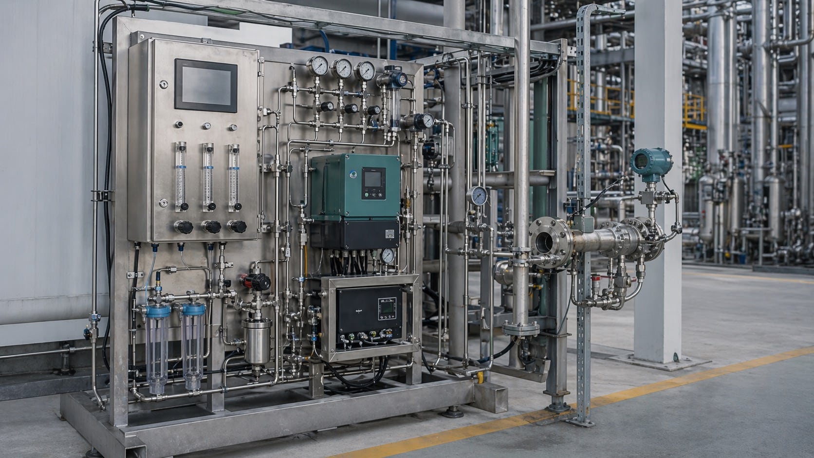
In-Situ Gas Analyzers
Two production-proven in-situ paths — paramagnetic direct-mount for combustion O₂ and cross-duct TDLAS for SCR/SNCR ammonia slip — where real-time feedback and low O&M decide the control loop.
GESHINE’s in-situ scope is deliberately focused. Combustion O₂ and NH₃ slip are the two duty profiles where a direct-mount or cross-duct optical path consistently holds up in production — stable matrix, tolerable dust, predictable window-purge behavior. For HCl, HF, moisture, chlorine, and multi-component duty, extractive conditioning delivers calibration predictability and a tractable maintenance cadence, and is the recommended GESHINE path.
When In-Situ Is the Right Installation Format
In-situ mounting solves specific measurement problems that extractive loops cannot — and understanding when each fits is the first step in analyzer selection.
Response Time Drives the Control Loop
Combustion trim, SCR/SNCR ammonia slip feedback, and safety interlocks depend on T90 under one second. Extractive sample transport adds 15–60 seconds of lag that can make the control loop unusable.
Reactive or Sticky Species
HCl, HF, NH₃, and H₂O adsorb onto heated sample line walls, condense in coolers, or react with fittings. Measuring in the live stream preserves the actual concentration that matters.
Low Maintenance Is a Hard Requirement
No sample pumps to service, no heated tubing to replace, no filters to change on a weekly rota. In-situ cuts the analyzer into two optical heads and a window-purge supply — dramatically fewer moving parts.
Clean Gas-Fired Ducts and Reformers
Modern natural-gas combustion, reformer outlets, and post-scrubber ducts typically have low dust loading and manageable moisture. These conditions suit an optical path measurement with standard window purge.
Representative Average Across the Duct
A cross-stack laser integrates concentration over the full optical path — one line-of-sight average instead of a single-point extractive probe that can miss stratified flow.
Fewer Auxiliary Systems to Certify
No sample line to insulate, no cooler to classify, no heated pump in the analyzer shelter — reducing hazardous-area certification scope and instrument-air load on the plant.
What In-Situ Gives You — and What It Demands
Advantages
-
No sample conditioning system required Remove the heated probe, heated line, cooler, pump, and filter train from the installation. The cost, footprint, and maintenance rota all collapse.
-
Sub-second T90 response No sample transport lag. The reading at the DCS reflects the concentration at the duct centerline in real time.
-
Preserves reactive and condensable species NH₃, HCl, HF, and H₂O are measured before they can adsorb on tubing walls or drop out in a cooler.
-
Low long-term O&M burden Optical head cleaning and periodic alignment checks replace weekly sample-system service visits.
Constraints
-
Duct geometry must permit opposing flanges Cross-duct optics need two aligned flanges at the right elevation with clear line of sight. Bends, obstructions, and short straight-run ducts can block the installation.
-
Optical alignment and thermal expansion Thermal growth and vibration deflect the beam. Large ducts benefit from active alignment compensation or a retro-reflector design to tolerate movement.
-
Window fouling and purge reliability Dust, condensate, and corrosive mists deposit on window surfaces. Instrument-air purge is mandatory, and purge reliability becomes a key uptime factor.
-
High dust or droplet loading reduces signal Above roughly 50 g/m³ dust or heavy droplet regimes, transmission drops and low-signal alarms become frequent. Extractive is usually a better choice in these streams.
Why the In-Situ Scope Is Focused
In-situ measurement demands a narrow matrix envelope — stable optical transmission, manageable dust and droplet loading, and predictable window-purge behavior. GESHINE deploys in-situ on paths where these conditions consistently hold: combustion O₂ where sub-second feedback drives burner trim, and SCR/SNCR NH₃ slip at catalyst outlets where dew-point drop-out would corrupt an extractive reading. Acid gases (HCl, HF), trace moisture, chlorine, and multi-component duty are routed through extractive conditioning — not because in-situ is impossible, but because heated sampling delivers the calibration predictability and maintenance cadence those applications need in production.
Considering in-situ for a gas not listed here? Our application engineers run a feasibility review — matrix assessment, optical path design, window-purge sizing — to tell you honestly whether an in-situ path is viable or whether an extractive train will serve you better. Request a feasibility review.
Current In-Situ-Ready Models
GESHINE’s in-situ scope currently prioritizes two production-proven paths. Each model below links to its analyzer category for specifications, application notes, and RFQ.
O₂Oxygen Analyzers
View All Oxygen AnalyzersZS8100-O2
ZS8100-O2 Process Oxygen Analyzer
High-accuracy paramagnetic O₂ measurement for process optimization
- Range
- 0-25 %vol O₂
- Accuracy
- ±0.05 %vol
- Response
- <5s T90
NH₃Ammonia Analyzers
View All Ammonia AnalyzersZS8100-NH3
Process Ammonia Analyzer
TDLAS ammonia slip analyzer for SCR/SNCR optimization and emission control
- Range
- 0–50 ppm NH₃ (configurable to 500 ppm)
- Accuracy
- ±0.5 ppm or ±2% of reading
- Response
- <2s T90
When In-Situ Is NOT the Right Choice
Honest engineering means naming where this installation format stops being the answer. In those cases extractive is the correct path forward.
Consider Extractive When…
- Dust loading is heavy (>50 g/m³) and cannot be purged off the windows reliably
- Cross-flow or droplet regime regularly saturates the optical path and triggers low-signal alarms
- The certification protocol assumes sample conditioning (some EPA Performance Specs, some EN methods)
- Multi-component speciation requires a conditioned-sample FTIR or GC-based analyzer
- Duct geometry does not permit opposing flanges, or insertion depth is unachievable
- The application needs periodic sample archival for laboratory cross-check
Extractive Gas Analyzers
For hostile matrices, regulated CEMS compliance, and multi-component speciation — extractive gas analyzers with the ZS-SCS sampling conditioning family handle what in-situ cannot.
- Heated sample line (180 °C) for wet, corrosive flue gas
- Cool-dry conditioning for clean, dry analyzer sample
- Regulated CEMS stacks with certified sampling protocols
- FTIR multi-component and FID total-hydrocarbon analyzers
In-Situ Gas Analyzer FAQ
Answers to the questions that typically surface during in-situ analyzer selection, sizing, and commissioning.
Why does GESHINE have fewer in-situ models than extractive?
In-situ measurement demands a narrow matrix envelope to stay reliable in production: stable optical transmission, tolerable dust and droplet loading, and predictable long-term window-purge behavior. GESHINE deploys in-situ on the paths where those conditions consistently hold — combustion O₂ (paramagnetic direct-mount) and SCR/SNCR NH₃ slip (cross-duct TDLAS) — and deliberately routes acid gases, trace moisture, chlorine, and multi-component duty through extractive sampling, where heated conditioning and controlled dew point deliver calibration predictability and a tractable maintenance cadence. The two formats are complementary, not redundant: in-situ for fast control where the matrix permits, extractive for everything else. If you have an application outside the current in-situ scope and want an independent feasibility review, our application engineers can run one.
What is an in-situ gas analyzer?
An in-situ gas analyzer mounts directly on the process duct or stack and measures gas concentration in the live stream without extracting a sample. A laser or light source is aimed across the duct from one flange to a receiver (or a retro-reflector) on the opposite side, and the beam interacts with the gas over the real duct cross-section. This eliminates sample transport lag, preserves reactive or condensable species, and removes an entire sample conditioning system from the analyzer scope.
When should I choose in-situ over extractive?
In-situ is the right call when response time matters (combustion trim, safety interlocks, SCR/SNCR ammonia slip feedback), when the species is reactive or sticky and does not survive a heated sample line (HCl, HF, NH₃, H₂O), and when the process conditions are hot but relatively clean (modern gas-fired stacks, reformer outlets, clean flue gas). Extractive is the safer choice when the matrix is heavily laden with dust or droplets, when regulated protocols require sample conditioning and validation, or when multi-component speciation requires a bench-style analyzer that only runs on a conditioned sample.
How fast is the response of an in-situ laser analyzer?
Cross-duct TDLAS systems typically deliver T90 response under 1 second because there is no sample transport delay — the laser interrogates the gas as it flows past the probe optics. For control loops on combustion or scrubber dosing, this sub-second response is often what justifies the in-situ choice over a 15–60 second extractive loop that includes heated tubing, cooler, filter, and pump transit time.
What limits in-situ analyzer performance?
Three constraints dominate. First, optical path stability: heavy dust, condensing moisture, or droplet formation reduces signal transmission and can trigger low-signal alarms. Second, duct geometry: the installation needs two opposing flanges at the right height and angle, with clear optical line of sight and tolerable alignment deflection from thermal expansion or vibration. Third, window fouling: corrosive or particulate-laden streams require purge-air window protection, and operators need to factor purge reliability into the long-term O&M plan.
Do I still need a sample system with an in-situ analyzer?
In most cases no — the whole point is to remove the sample conditioning loop. What you typically still need is a small instrument-air supply for window purge, a local calibration interface for span and zero verification, and sometimes a validation cell for periodic cross-check. For hybrid installations where the in-situ beam covers the primary measurement and a secondary extractive loop handles calibration or backup, the ZS-SCS family can be co-specified alongside the analyzer.
When is in-situ NOT a good fit, and should I move to extractive?
Move to extractive when the duct is heavily loaded with dust or water droplets that cannot be reliably purged, when the measurement must be certified under a protocol that assumes sample conditioning (some US EPA performance specs, some EN standards for specific pollutants), when you need simultaneous multi-component analysis that only a conditioned-sample FTIR or GC-based analyzer can provide, or when the duct geometry simply does not permit opposing flanges. See the Extractive Gas Analyzers page for the sample-conditioned alternative.
Application outside the current in-situ scope?
Send your matrix to an application engineerRequest a Quote for In-Situ Gas Analyzers
To configure the right in-situ analyzer for your process, please have these details ready:
- Target gas and expected concentration range
- Duct diameter and available flange locations
- Process temperature, pressure, and dust loading
- Moisture / droplet regime at the measurement point
- Instrument-air supply availability for window purge
- Hazardous area classification (ATEX zone, if applicable)
- Output protocols (4-20 mA, Modbus RTU/TCP, HART)
- Required certifications (CE, SIL, MCERTS, EN 15267)

Talk to an In-Situ Specialist
Our application engineers specialize in cross-duct TDLAS alignment, window-purge design, and ATEX-rated in-situ probes for heavy industry.