
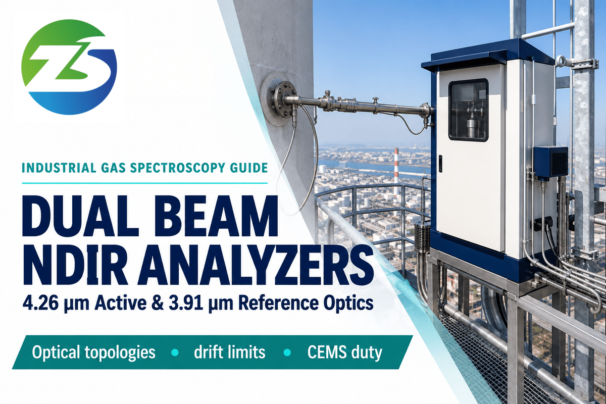
A dual beam ndir analyzer splits an active gas absorption signal by a simultaneous neutral reference channel near 3.91 µm. Dust and age on infrared lamps can be canceled by regular ratioing. A 24/7 industrial stream makes this maintenance easier. In a single beam module, a 7-14 day fresh air baseline is assumed. This assumption does not always hold true. It does not hold true in continuously occupied rooms, greenhouses, and in the ducts that exhaust buildings (as reported by Senseair engineering notes). Zero drift is not always eliminated by adding a second optical channel. Other factors like blackbody filament cooling, detector thermal mismatch, and moisture in the sample need to be accounted for as well, especially when specifying a dual beam ndir gas analyzer. False baseline readings can be very costly.
Key Engineering Takeaways
- Dividing the 4.26 µm active channel by the 3.91 µm reference channel gives ratiometric drift cancellation. It cancels 15% to 25% common mode lamp dimming with 0 ppm net error, which is described in US8178832B1.
- Optical hardware trade-offs result in differing hardware topologies between dual-detector modules and dual-source modules. Dual-source modules, for example, pulse the reference emitter ~40,000 times less frequently than dual-detector modules (43,200:1 to 172,800:1, daily at 0.5 – 2 Hz), according to Senseair.
- Four uncompensated error boundaries pass through the 3.91 µm ratio: Planck filament temperature shifts, differential detector drift, liquid water films, and cross-gas band overlap, as shown in US8178832B1 . More information can be found in US8178832B1.
- At a 10–15 s response time (T90), trace detection stepping separates standard filter benches (1–10 ppm) from GFC (0.04–0.5 ppm) and TDLAS (0.05–1 ppm) in 10–15% CO2, per POWER Magazine.
- Continuous “duty-cycle and regulatory rules” show that 7- to 14-day single-beam auto-calibration cause a ~600 ppm downward offset in 1,000 ppm rooms. Compliance stacks require 24-hour U.S. EPA or European EN 14181 QAL3 weekly CUSUM/EN 15267 QAL1 Shewhart checks, according to 40 CFR Part 60 Appendix F.
How Dual-Beam NDIR Works: Active Absorption Wavelength (4.26 µm) vs. Neutral Reference Channel (3.91 µm)
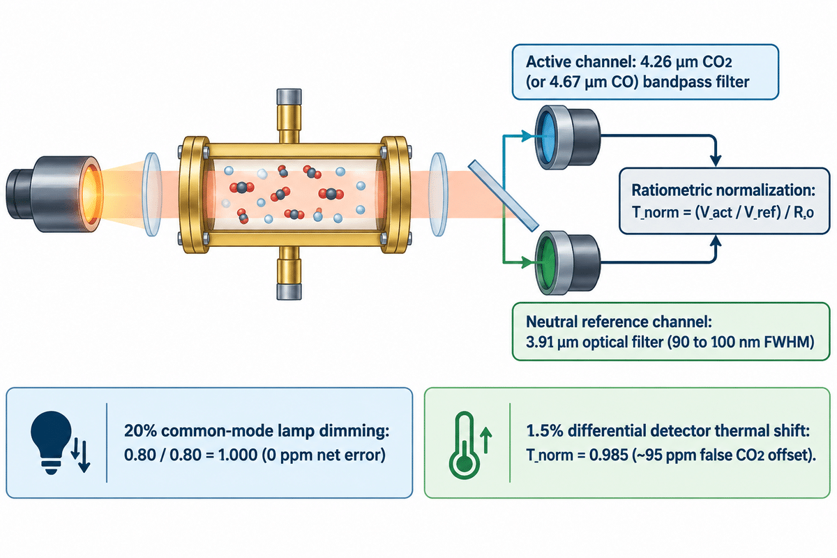
A dual-beam NDIR gas analyzer divides the active gas-absorption signal (4.26 µm for CO2 or 4.67 µm for CO) by a neutral 3.91 µm reference signal. Common-mode infrared lamp aging and uniform window dust attenuation are eliminated in this measurement as the target gases don’t absorb at the 3.91 µm wavelength.
The non-dispersive infrared detection method relies on absorption of infrared radiation located in a gold-plated sample chamber. Heteronuclear gas molecules absorb mid-infrared photons across the electromagnetic spectrum at discrete quantum energies. According to Electro Optics detector design benchmarks, detection of carbon dioxide targets the 4.2 to 4.26 µm infrared absorption band. A narrowband band-pass filter in front of the active infrared detector isolates this spectral window for infrared spectroscopy. Meanwhile, the reference channel uses a 3.91 µm optical filter with a 90 to 100 nm full width at half maximum (FWHM). Neither carbon dioxide nor water vapor absorbs infrared light around 3.91 µm. Therefore, due to variation of gas concentration with molecular density, active controls of temperature and barometric pressure compensation are employed in industrial benches as well.
How does a dual beam NDIR gas analyzer use its 3.91 µm reference wavelength channel to compensate for source aging?
The analyzer normalizes transmittance by dividing the 4.26 µm active voltage by the 3.91 µm reference voltage and scaling by the zero-gas calibration ratio. These factors account for filament darkening, and window dust. Common-mode attenuation, resulting from filament darkening and dust on broad band windows, is cancelled in the Beer-Lambert equation.
As documented in USPTO Patent US8178832B1, single-channel photometry follows the monochromatic Beer-Lambert relationship I = I0 exp(-alpha * c * L). Here, alpha represents the absorption coefficient, c is the target gas concentration, and L is the optical path length. When the infrared source dims by 20% over two years, a single-channel sensor misinterprets that lost flux as gas absorption, as documented in US8178832B1. Inside a dual-channel bench, the processor tracks the normalized ratio T_norm = (V_act / V_ref) / R_0. That Beer-Lambert synthesis proves why a 20% common-mode source decay produces 0 ppm net error in T_norm = (V_act / V_ref) / R_0. By contrast, a 1.5% differential detector/filter thermal shift creates a ~95 ppm false CO2 offset, paired with the 3.9 µm Reference Compensation Boundary. The baseline factor R_0 = V_act,0 / V_ref,0 is recorded during pure nitrogen zeroing:
- With common-mode lamp dimming (20% drop), both Vact and Vref scale by 0.80. The ratio 0.80 / 0.80 is 1.000, and thus net zero error is 0 ppm, as documented in US8178832B1.
- Under a differential detector shift (1.5% uncompensated), ambient thermal gradients shift V_act by -1.5% while V_ref stays constant. That drops T_norm to 0.985 and creates an immediate ~95 ppm false offset on a 0 to 2,000 ppm bench, as modeled in US8178832B1.
| Target Process Gas | Center Wavelength (CWL) | Typical Filter FWHM | Primary Spectral Interferent | Reference Channel Pairing |
|---|---|---|---|---|
| Carbon Dioxide (CO2 / CO₂) | 4.26 µm | 120–140 nm | Minimal (isolated band) | 3.91 µm neutral window |
| Carbon Monoxide (CO) | 4.67 µm | 90–140 nm | CO2 wing at 4.26 µm & N2O at 4.5 µm | 3.91 µm or GFC correlation cell |
| Methane & Hydrocarbons (CH4) | 3.31–3.40 µm | 100–160 nm | C2H6 / C3H8 C-H stretch overlap | 3.91 µm neutral window |
| Nitric Oxide (NO) | 5.30 µm | 100–150 nm | Water vapor (6.3 µm band edge) | 3.91 µm + Peltier drying |
| Sulfur Dioxide (SO2) & Sulfur Hexafluoride (SF6) | 7.35 µm (SO2) / 10.5 µm (SF6) | 150–200 nm | Water vapor (6.3 µm) & NO2 | 3.91 µm or dual-cell chopper |
Three Reference-Channel Hardware Topologies: Dual-Detector Split-Filter, Dual-Source Single-Detector, and Chopper-Wheel
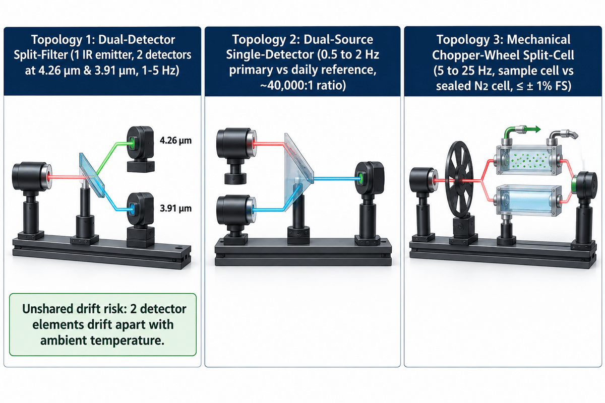
Commercial gas analyzers use three different optical architectures to implement a dual-detector reference compensation mechanism: a single-source, dual-detector package; a dual-source, single-detector module; and a mechanical chopper-wheel split-cell bench. All three architectures eliminate one primary drift variable and leave a different unshared optical component vulnerable to aging.
Catalog datasheets commonly lump these three architectures together. However, in the design of integrated micro-module gas detector transmitters and 19″ rack analyzers, different ndir technology and gas concentration measurement are employed. Published testing in MDPI Sustainability (2024) and bench-top multi-gas trials in Infrared Physics & Technology (2025) show that the stability of a zero and design of the bench are key in achieving accuracy. Instrumentation engineers identify three different compensation arrangements, of which the first is a dual-detector bench with a single source.
- First, topology 1, a dual detector split filter (single source, dual detectors) architecture, employs a single pulsed micro bulb or MEMS emitter to excite a gas tube. At the other end, a TO-39 can houses two detectors, which are separated by 4.26 µm and 3.91 µm optical filters. Combining an infrared light source and a thermopile detector pair reduces moving parts and improves power consumption. However, the two detector elements drift apart with changes in ambient temperature.
- Second, Topology 2, Dual-Source Single-Detector (Two Emitters, One Detector) places two infrared sources inside a single optical cavity with one detector fitted with a 4.26 µm filter. The primary lamp fires at 0.5 to 2 Hz while the reference lamp fires once per day (a 43,200:1 to 172,800:1 daily ratio). That schedule matches the approximate 40,000:1 lifetime firing ratio reported by Senseair. Since both beams strike the same detector, differential detector drift is eliminated, however, cavity wall dust is not compensated for.
- Third, Topology 3 – Mechanical Chopper-Wheel Split-Cell (Industrial Extractive Bench) uses a nichrome emitter with a motor-driven modulation disc (5 to 25 Hz) to chop a radiation beam. The beam is split by a flowing sample cell and a sealed nitrogen reference cell. Both beams converge to a single detector. This true dual-path bench achieves high signal-to-noise ratio, and ≤ ± 1% full-scale repeatability (reported in Fuji Electric ZKJ/ZRE specifications) though the chopper motor adds mechanical wear.
| Hardware Topology | Shared Optical Elements | Unshared Drift-Prone Elements | Modulation Method | Primary Industrial Form Factor |
|---|---|---|---|---|
| Dual-Detector Split-Filter | 1 IR emitter, 1 gas cell | 2 detector elements, 2 narrowband filters | Electronic pulsing (1–5 Hz) or kHz LED | OEM PCB modules & fixed transmitters |
| Dual-Source Single-Detector | 1 detector element, 1 bandpass filter | 2 emitters (~40,000:1 lifetime / 43,200:1–172,800:1 daily ratio) | Alternating electronic lamp pulsing (0.5–2 Hz vs. daily) | Commercial HVAC & greenhouse monitors |
| Chopper-Wheel Split-Cell | 1 IR source, 1 detector element | Sample vs. sealed N2 cell windows, chopper motor | Mechanical rotating wheel (5–25 Hz) | 19-inch rack extractive & CEMS analyzers |
What the Reference Channel Compensates, and the 4 Drift Errors It Cannot Cancel Out
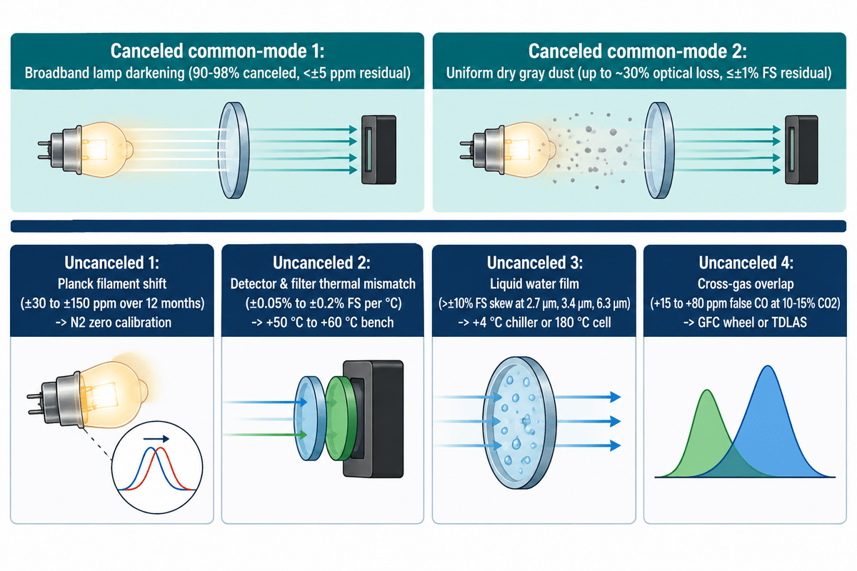
A 3.91 µm reference channel balances dimming of the broadband emitters, uniform gray window dust, and fluctuations in the power-rail. It can’t balance Planck blackbody spectral shifts, differential detector drift, liquid water films, and cross-gas band overlap.
In our experience, most plant engineers believe that non-dispersive IR sensor (or ndir co2 gas sensor) instruments guarantee long-term stability and accuracy and precision without nitrogen zeroing. However, independent atmospheric studies in the Journal of Atmospheric and Oceanic Technology and side-by-side sensor testing by SeeTheAir demonstrated the contrary. Ratiometric division removes only errors that scale both wavelengths on the calibration curve by the same factor. As long as physical degradation alters the 4.26 µm signal in the same manner as the 3.91 µm signal, the ratio remains stable.
The 3.9 µm Reference Compensation Boundary
To review vendor claims during hazard and operability studies, we define the 3.9 µm Reference Compensation Boundary. This engineering boundary separates two identical disturbances in calibration (canceled by V_act/V_ref) from four differential drift mechanisms that go directly through the ratio:
- During Planck Blackbody Filament Temperature Shift, vaporization of tungsten filament alters the color temperature of the emitter, as proven in US8178832B1 and US8866085B1. By Wien’s displacement law, a cooler filament shifts the blackbody radiation slope between 3.91 µm and 4.26 µm. Stopping this drift requires performing a zero calibration or an absorption-biased identical filter cell (US20110042570A1).
- Under Differential Detector and Filter Thermal Drift, the two thermopile or InAsSb elements in dual-detector packages exhibit slight temperature coefficient mismatches. Those mismatches are typically in the range of ±0.05% to 0.2% per °C, as reported in Electro Optics. Dielectric interference coatings also shift their center wavelength by about 0.2 to 0.4 nm, for an ambient temperature swing of 10 °C.
- According to Wavelength-Selective Window Films and Condensation, dry carbon soot absorbs 3.91 µm and 4.26 µm almost equally. Liquid water films and hydrocarbon mists on the other hand absorb strongly near 2.7 µm, 3.4 µm, and 6.3 µm, causing one filter channel to skew far more than the others. For pipeline dew point limits, refer to our natural gas moisture analyzer and water dew point conditioning guide.
- Under Cross-Gas Spectral Wing Overlap and Pressure Broadening, a 3.91 µm reference filter is blind to interferent gases absorbing inside the active passband. Specifically, 10% to 15% flue-gas CO2 has rotational wings that bleed into a 4.67 µm carbon monoxide filter, as reported in POWER Magazine. Barometric pressure swings similarly alter molecular density and Lorentz line broadening without changing the 3.91 µm signal.
| Disturbance Source | Spectral Mode | Canceled by 3.91 µm Ratio? | Uncompensated Error Magnitude | Required Engineering Countermeasure |
|---|---|---|---|---|
| Broadband lamp envelope darkening | Common-mode | Yes (roughly 90–98% canceled, as documented in US8178832B1) | <±5 ppm residual | Standard V_act / V_ref ratiometric division |
| Uniform dry gray dust on windows | Common-mode | Yes (up to ~30% optical loss, as documented in US8178832B1) | ≤±1% FS residual (published by GESHINE) | 0.1–2 µm upstream PTFE particulate filter |
| Planck filament temperature shift | Differential slope | No (as documented in US8178832B1) | Typically ±30 to ±150 ppm over 12 months | Periodic N2 zero calibration or identical-filter cell |
| Detector & filter thermal mismatch | Differential gain | No (as reported in Electro Optics) | Typically ±0.05% to ±0.2% FS per °C | Thermostated optical bench (+50 °C to +60 °C) |
| Liquid water or oil film on optics | Wavelength-selective | No (as reported in EPA Part 75 Manual) | Typically >±10% FS permanent skew | +4 °C Peltier chiller, Nafion dryer, or 180 °C hot-wet cell |
| Cross-gas band overlap & pressure | In-band interference | No (as reported in POWER Magazine) | Typically +15 to +80 ppm false CO at 10–15% CO2 | Step up to GFC wheel or TDLAS + pressure transducer |
Comparing Optical Gas Sensing Topologies: Dual-Detector NDIR vs. Dual-Source NDIR vs. GFC and TDLAS
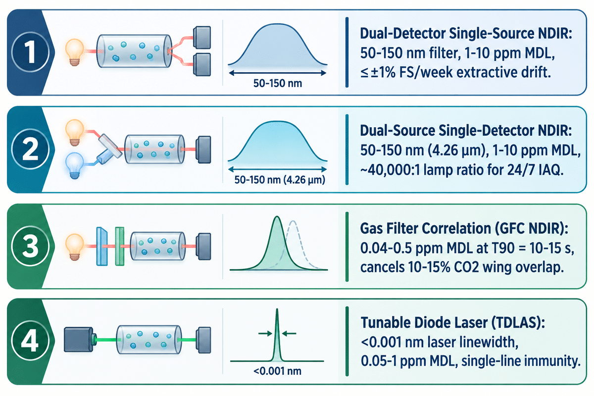
Standard CO2 and CO dual-beam NDIR channels use 50-150 nm bandpass filters (members of the 90-200 nm mid-IR filter family, tabulated in Table 1) to achieve 1-10 ppm detection limits. Gas Filter Correlation (GFC) analyzers achieve 0.04-0.5 ppm, with higher CO2 rejection, and TDLAS lasers (<0.001 nm linewidth) achieve 0.05-1 ppm, with no cross-interference.
Selecting an infrared gas analyzer for air pollution control requires matching spectral resolution to your parts-per notation range and background gas matrix. A 90 to 140 nm filter covers dozens of individual rotational lines and the gaps in between. For accurate gas measurement of percent-level co2 gas or clean methane, filter-based co2 sensors remain cost-effective across sensor types. However, combustion stacks require trace ndir co measurement (0 to 50 ppm) within 10% to 15% CO2 and water vapor. Under those conditions, standard filter passbands suffer severe cross-sensitivity. As reported by POWER Magazine and codified in 40 CFR Part 60 Appendix B Performance Specification 4A, trace combustion monitoring demands higher spectral selectivity.
How do dual-detector NDIR, dual-source NDIR, gas filter correlation (GFC), and TDLAS compare in zero drift and detection limit?
At a matched 10 to 15 second response time of the sensor (T90), dual-beam NDIR benches achieve the 1-10 ppm detection limit, GFC achieves 0.04-0.5 ppm and TDLAS achieves 0.05-1 ppm. On GESHINE extractive benches, linear drift stays within ≤±1% FS per week, with ≤±1% FS repeatability.
Compared to the NDIR designs that use single detectors, dual-detector split-filter sensors divide photon flux over two detectors. This arrangement reduces signal to noise and exposes the bench to differential detector thermal drift. Dual source modules with a single detector compensate for detector mismatch by using a shared detector (~40,000:1 emitter firing ratio) and leave wall tarnish uncompensated, as reported by Senseair. In a Gas Filter Correlation bench, infrared radiation passes through a spinning wheel that holds one high-concentration gas cell (100% CO) and one nitrogen cell. Background CO2 cancels out through both halves of the wheel. For contact-free sampling, precise measurement, engineers use the laser absorption spectroscopy, in combination with narrow-linewidth TDLAS gas analyzers, for sub-ppm trace detection measurements. Plants measuring process streams that are free of impurities, use dedicated extractive CO and CO2 infrared gas analyzers. For measuring oxides of nitrogen, along with sulfur dioxide and oxygen, in combination with infrared benches, stack operators use paramagnetic or zirconia oxygen cells in conjunction with a chemiluminescence analyzer.
The 4-Topology Optical Bench Selector
Use the 4-Topology Optical Bench Selector below to match filter bandwidth, detection limit, and cross-gas rejection at a matched T90 = 10 to 15 s integration window.
| Optical Sensing Topology | Effective Spectral Bandwidth | Minimum Detection Limit (T90 = 10–15 s) | Repeatability & Drift Profile | CO2 / H2O Cross-Rejection | Optimal Process Duty |
|---|---|---|---|---|---|
| Dual-Detector Single-Source NDIR | 50–150 nm (CO2/CO); 90–200 nm family | 1–10 ppm (path-dependent) | ≤±1% FS repeatability; ≤±1% FS/week extractive drift (published by GESHINE) | Moderate (requires +4 °C dry gas) | 200 ppm to 100% vol CO2, CH4, syngas |
| Dual-Source Single-Detector NDIR | 50–150 nm filter FWHM (4.26 µm) | 1–10 ppm (bench-dependent) | Cancels detector mismatch; ~40,000:1 lamp ratio leaves cavity dust uncompensated (reported by Senseair) | Low (clean ambient air only) | 24/7 cleanrooms, greenhouses, IAQ |
| Gas Filter Correlation (GFC NDIR) | Rotational fine-line gas cell match | 0.04–0.5 ppm | ≤±1% FS repeatability; ≤±1% FS/week on GESHINE extractive benches | High (cancels 10–15% CO2 wing overlap) | 0–50 ppm trace CO, NO, N2O, SO2 CEMS |
| Tunable Diode Laser (TDLAS) | <0.001 nm laser linewidth | 0.05–1 ppm | ≤±1% FS repeatability; line-locked laser wavelength stability (published by GESHINE) | Immunity (single rotational-vibrational line) | Trace H2O, NH3, HCl, H2S, CH4 stacks |
Duty-Cycle Selection: Why Single-Beam ABC Fails in 24/7 Industrial Rooms, Greenhouses, and CEMS Stacks
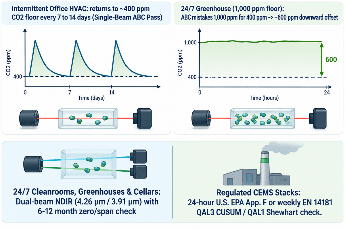
Single-beam NDIR sensor instruments with Automatic Baseline Calibration (ABC) assume ambient CO2 drops to 400 ppm at least once every 7 to 14 days. In continuously occupied rooms and 1,000 ppm greenhouses, this false assumption causes a ~600 ppm downward baseline error.
Low-cost commercial indoor air quality monitors used for heating, ventilation and air conditioning, use a single infrared source and one detector without a reference channel. To mask lamp aging drift, their firmware runs an auto-calibration algorithm, over a rolling 7 to 14 day window, as reported by Munro Scientific and Analox Group. For single-beam ndir co 2 monitors, the firmware records the lowest observed co 2 concentration over 7 to 14 days and forces it to 400 ppm. In a building where an office empties out each weekend, ventilation air sets the room to 400 ppm and the algorithm kicks in. In 24/7 occupied industrial enclosures, agricultural rooms and/or process ducts, this is not the case.
When should you specify a dual beam NDIR sensor instead of a single beam sensor with automatic baseline calibration (ABC)?
A dual-beam NDIR architecture should be specified whenever the monitored space does not flush to ~400 ppm fresh outdoor air within the firmware’s 7 to 14 day rolling ABC window. Dual-beam or GFC optics are also required for process gases (CO, CH4, SO2) and regulated CEMS stacks.
Let’s say a controlled environment greenhouse or mushroom cultivation room maintains a minimum carbon dioxide sensor floor of 1,000 ppm 24 hours a day. After 7 to 14 days, a single-beam ABC module mistakes 1,000 ppm as 400 ppm air and applies a ~600 ppm downward offset, as stated by Munro Scientific. When the true room concentration reaches 1,500 ppm, the display shows only 900 ppm. Under-reporting CO2 in brewery cellars or safety leak detection zones creates a severe hazard, and requires 6 to 12 month zero/span checks on a dual-beam sensor, as described in US8178832B1. Process streams monitored by multi-component syngas analyzers contain high % CO and CO2 continuously. While, for compliance CEMS stacks, 24-hour U.S. EPA drift checks or European EN 14181 QAL3 weekly CUSUM / EN 15267 QAL1 Shewhart checks must be performed, as stated in 40 CFR Part 60 Appendix F.
| Duty Category & Facility Class | Minimum Gas Floor (7–14 Day Window) | Single-Beam ABC Outcome | Recommended Analyzer Type & Tier | Zero & Span Verification Protocol |
|---|---|---|---|---|
| Class 1: Intermittent Office / School HVAC | ~400 ppm CO2 overnight flush | Pass (returns to 400 ppm floor) | Single-beam NDIR or photoacoustic sensor | 7–14 day rolling firmware ABC (reported by Senseair) |
| Class 2: 24/7 Hospital / Control Room IAQ | Elevated CO2 (>400 ppm continuous) | Fail (downward false-zero drift) | Dual-beam NDIR (4.26 µm / 3.91 µm) | ABC disabled; 6–12 month zero/span gas check |
| Class 3: CO2-Enriched Greenhouse / Mushroom Room | ≥1,000 ppm CO2 continuous floor | Fail (~600 ppm downward offset, reported by Munro) | Dual-beam NDIR wall transmitter | 6–12 month zero/span cylinder or fresh-air check |
| Class 4: Brewery / Winery Fermentation Cellar | Elevated CO2 safety monitoring | Fail (unsafe under-reporting) | Fixed dual-beam NDIR safety detector | 6–12 month certified N2 zero & span verification |
| Class 5: Anaerobic Digester Biogas Skid | Continuous % vol CH4 & CO2 stream | Fail (zero atmospheric baseline) | Cold-dry extractive dual-beam NDIR bench | ≤±1% FS/week drift; periodic N2 zero & 6–12 month bench service |
| Class 6: Coal / Biomass Gasification Syngas | Continuous CO, CO2, CH4 (0–100% vol) | Fail (requires extractive conditioning) | 19-inch rack dual-beam NDIR + O2 analyzer | ≤±1% FS/week drift (published by GESHINE); scheduled N2/span check |
| Class 7: Trace Combustion CO in 10–15% CO2 | 0–200 ppm CO with 10–15% CO2 wing | Fail (cross-gas spectral overlap) | Gas Filter Correlation (GFC) NDIR bench | 24-hour auto-zero/span or weekly QAL3 check |
| Class 8: U.S. Stationary Stack CEMS (40 CFR 60) | Continuous flue gas SO2, NOx, CO, CO2, O2 | Illegal under 40 CFR Part 60 App. B/F | Turnkey CEMS dual-beam NDIR / GFC cabinet | Mandatory 24-hour zero/span drift check + quarterly CGA + annual RATA |
| Class 9: European Stack CEMS (EN 14181 QAL3) | Continuous regulated stack emissions | Illegal under EN 14181 / EN 15267 | QAL1-certified extractive NDIR / GFC / TDLAS | Weekly zero/span (CUSUM) or QAL1 maintenance interval (Shewhart) |
Extractive Sample Conditioning, Industrial NDIR Manufacturers, and RFQ Specification Protocol
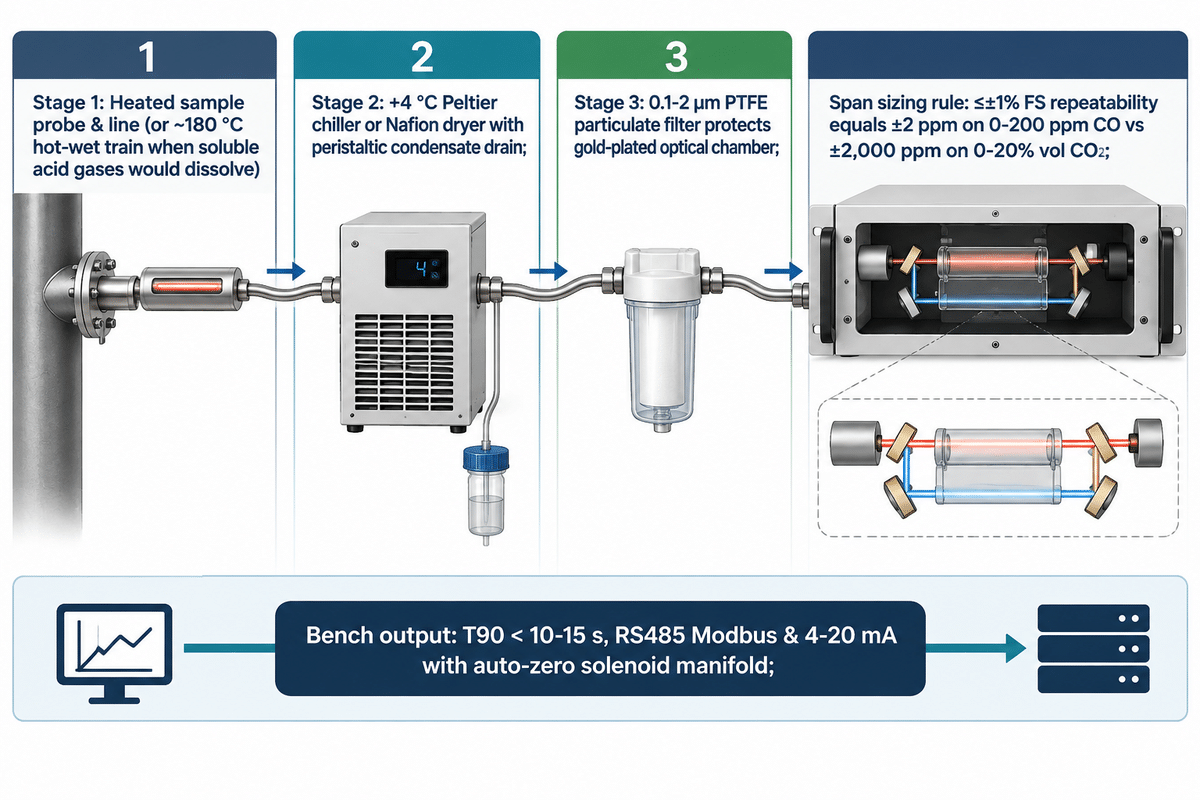
Cold-dry extractive dual-beam NDIR analyzers require a heated sample probe, a +4 °C Peltier chiller or Nafion membrane dryer, and 0.1 to 2.0 µm PTFE particulate matter filtration. Hot-wet (~180 °C) or dilution extractive trains are used when water-soluble acid gases would dissolve in chiller condensate.
Optical ratioing only compensates for dry, non-selective dust in the optical chamber. When synthesis gas or flue gas contains water and particles, unconditioned sample gas condenses on gold mirrors or corrodes carbon steel. Under the U.S. EPA Part 75 CEMS Field Audit Manual (§2.3), plants classify three architectures. Cold-dry systems use a +4 °C Peltier condenser or Nafion permeation dryer, hot-wet systems heat sample lines and cells to ~180 °C, and dilution systems mix dry instrument air. Inside cold-dry chillers, water-soluble SO2 and NO2 partially dissolve in the condensate water. A rapid separation peristaltic pump, a Nafion dryer, or a hot-wet bench would remedy the condensate issue. Cold-dry benches also measure on a dry basis, rather than a wet stack basis. For complete information on all the architectural components of a CEMS system, reference our CEMS Analyzers: Heated Extractive Sample Conditioning Architecture guide.
Which manufacturers supply industrial dual beam NDIR gas analyzers and multi-gas infrared benches for CEMS and syngas?
Verified suppliers of 19-inch rack and CEMS dual-beam NDIR analyzers, per our benchmark dataset, include Fuji Electric (ZKJ and ZRE series), GESHINE (extractive dual-beam NDIR, GFC, and TDLAS multi-gas analyzers), and HORIBA. OEM sensor modules and mid-IR detector/emitters are provided by Senseair, Winsen, and Hamamatsu Photonics.
When comparing vendor datasheets, always check the full-scale span denominator behind the repeatability specification. Both Fuji Electric ZKJ/ZRE analyzers (measuring NO, SO2, CO, CO2, and CH4 plus O2 across 0–200 ppm to 0–100% vol ranges) and GESHINE extractive benches specify measurement accuracy and repeatability as ≤±1% of full scale (FS). On a 0 to 200 ppm trace CO channel, ±1% FS equals ±2 ppm. On a 0 to 20% volume (200,000 ppm) syngas CO2 channel, ±1% FS equals ±2,000 ppm, requiring independent low-range and high-range channels. Those 19-inch rack and CEMS cabinet configurations measure CO, CO2, CH4, SO2, and NOx plus paramagnetic/electrochemical O2 with ≤±1% FS repeatability and T90 < 10–15 s. Each chassis integrates +4 °C Peltier sample conditioning, 0.1–2 µm PTFE filtration, and RS485 Modbus / 4–20 mA outputs for wide range of applications in environmental monitoring.
| Manufacturer & Equipment Tier | Model / Series Designation | Analyzer Type & Optical Topology | Documented Target Gases / Wavelengths | Verified Performance Benchmark |
|---|---|---|---|---|
| Fuji Electric (Rack Analyzer Tier) | ZKJ / ZRE Series | 19-inch rack dual-beam NDIR multi-gas analyzer | NO, SO2, CO, CO2, CH4 + O2 (0–200 ppm to 0–100% vol) | ≤±1% FS repeatability (published by Fuji Electric) |
| GESHINE (Extractive NDIR Tier) | Extractive Dual-Beam NDIR Series | 19-inch rack & CEMS cabinet cold-dry extractive NDIR | CO, CO2, CH4, SO2, NOx + paramagnetic / electrochemical O2 | ≤±1% FS repeatability; ≤±1% FS/week drift; T90 < 10–15 s (published by GESHINE) |
| GESHINE (Trace GFC Tier) | Extractive GFC NDIR Series | Gas Filter Correlation wheel + +4 °C Peltier conditioning | Trace CO (4.67 µm), NO, SO2, CO2 in high-CO2 flue gas | 0.04–0.5 ppm MDL at T90 = 10–15 s; ≤±1% FS repeatability (published by GESHINE) |
| GESHINE (Laser TDLAS Tier) | Extractive & Process TDLAS Series | Tunable diode laser (<0.001 nm linewidth) analyzer | Single-line trace gas channels + multi-gas CEMS integration | 0.05–1 ppm MDL at T90 = 10–15 s; zero cross-interference |
| HORIBA (Industrial Bench Tier) | Industrial Chopper NDIR Benches | Rotating chopper-wheel / gas-cell modulation NDIR | CO, CO2, CH4, SO2, NOx process & stack monitoring | High SNR dual-path modulation (documented in research journal) |
| Senseair (OEM Sensor Tier) | Dual-Channel NDIR Modules | Two-emitter single-detector & single-emitter two-detector | CO2 (4.26 µm active / 3.91 µm reference) for 24/7 spaces | ~40,000:1 primary-to-reference emitter firing ratio |
| Winsen (OEM Module Tier) | Dual-Beam NDIR Sensor Series | Compact PCB dual-wavelength NDIR gas sensor modules | CO2 (4.26 µm), CO (4.67 µm), CH4 (3.31 µm), SF6 (10.5 µm) | Dual-channel filter compensation vs. single-beam modules |
| Hamamatsu (Thermopile Detector Tier) | T11722-11 / T11722-12 Series | Dual-channel thermopile detector with integrated filters | 4.26 µm CO2 sensing CWL + 3.9 µm reference CWL | 50 V/W thermopile sensitivity (published by Hamamatsu) |
| Hamamatsu (Quantum & LED Tier) | P16849 / P16112 & L15895 / L15894 | InAsSb photovoltaic detectors & solid-state mid-IR LEDs | 4.3 µm active LED & 3.9 µm reference LED (10 µs pulses) | 15 ns response, 3.2 mA/W sensitivity, 5.3x lock-in SNR gain |
Your procurement request for quotation (RFQ) should include the following 6-point engineering specification table to ensure the sampling conditioners you receive aren’t undersized and to avoid span mismatches.
RFQ checklist — copy these into your quote request (data from GESHINE & 40 CFR Part 60):
| Parameter | Recommended range | Why it matters | How to verify |
|---|---|---|---|
| Optical Bench Topology | Dual-beam 4.26/3.91 µm (1–10 ppm MDL) or GFC (0.04–0.5 ppm) | Prevents 10–15% CO2 wing bleed into trace CO channels, as reported in POWER Magazine | Optical bench datasheet & cross-interference test certificate |
| Full-Scale Span & Repeatability | Independent low/high spans; ≤±1% FS repeatability (published by GESHINE) | 1% FS on 0–20% vol equals ±2,000 ppm error vs ±2 ppm on 0–200 ppm | Factory linearity & repeatability calibration protocol |
| Extractive Sample Conditioning | +4 °C Peltier chiller or Nafion dryer; ~180 °C hot-wet if soluble | Protects mirrors while preventing SO2/NO2 condensate loss, per the standard EPA Part 75 Manual | P&ID review of dew point sensor alarm & peristaltic drain |
| Particulate Filtration & Flow | 0.1–2 µm PTFE particulate filter (published by GESHINE) | Stops sub-micron fly ash from coating gold sample chamber | Filter element specification sheet & sample flow rate alarm test |
| Pressure & Temperature Compensation | Active cell temperature & absolute barometric pressure sensors | Corrects ideal-gas density and filter thermal wavelength shift, as documented in US8178832B1 | Barometric pressure & thermal step-test report during FAT |
| Telemetry & Auto-Zero Solenoids | RS485 Modbus + 4–20 mA; automated zero/span solenoid manifold | Automates 24-hour EPA App. F or weekly EN 14181 QAL3 drift checks, per the standard | PLC register map & solenoid timer sequence test at FAT |
2026 Dual-Beam NDIR Price Tiers (OEM Sensor Module vs. 19-Inch Rack Analyzer) and Calibration Gas Schedule
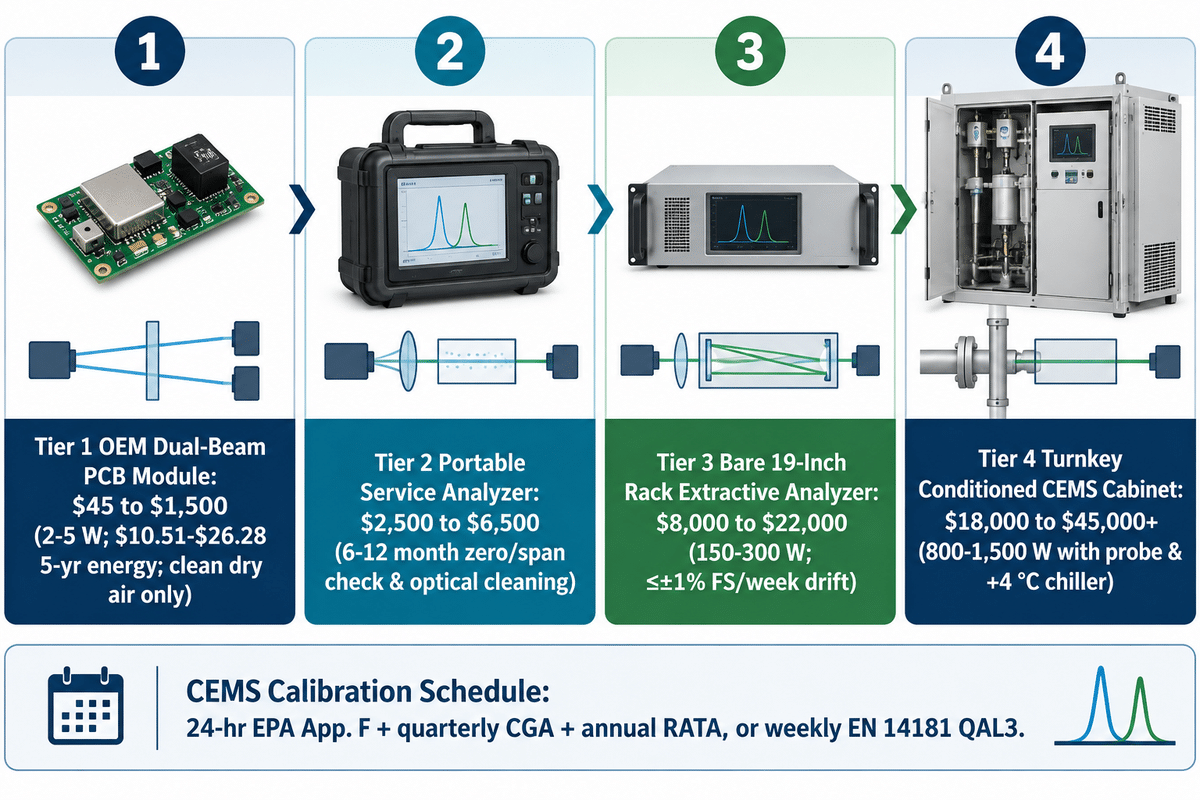
Across industrial analyzer market benchmarks, board-level dual-beam NDIR sensor modules cost $45 to $1,500 and portable service analyzers cost $2,500 to $6,500, as reported in our benchmark dataset. Bare 19-inch rack extractive multi-gas analyzers cost $8,000 to $22,000, while turnkey CEMS cabinets with Peltier chiller sample conditioning range from $18,000 to $45,000+.
“Once every 24 hours, analyze the mid-level calibration standard for each analyte.”
Procurement teams underestimate lifecycle cost by confusing an unconditioned PCB detector module with an industrial extractive monitoring system. Even with a dual-beam optical bench, compliance analyzers can’t skip cylinder gas verification. Under U.S. EPA 40 CFR Part 60 Appendix F and IDEM CEMS Guidance, stationary stack operators run an automated zero and upscale drift check every 24 hours. The U.S. audit schedule also requires quarterly Cylinder Gas Audits (CGA) and an annual Relative Accuracy Test Audit (RATA), per 40 CFR Part 60 Appendix F. European plants under EN 14181 QAL3 (such as UK M20 §4.5) run weekly zero and span checks when plotting CUSUM control charts, per the standard EN 14181. Plants plotting Shewhart charts follow the maintenance interval certified during EN 15267 QAL1 testing, per the standard EN 15267. Non-CEMS industrial rooms, cleanrooms, and greenhouses verify zero and span every 6 to 12 months, matching the 6 to 12 month bench cleaning interval documented in US8178832B1.
What is the price difference between an OEM dual beam NDIR sensor module and a rack-mount extractive analyzer with sample conditioning?
As reported in industrial analyzer benchmarks, OEM dual-beam NDIR sensor modules cost $45 to $1,500 and portable service analyzers cost $2,500 to $6,500. By contrast, bare 19-inch rack extractive multi-gas analyzers cost $8,000 to $22,000, and turnkey conditioned CEMS cabinets cost $18,000 to $45,000+.
The hardware price progression across these four tiers reflects sample conditioning trains, thermostated optical cavities, and regulatory certification, as reported in GESHINE analyzer documentation. A compact ndir PCB module ($45 to $1,500, data from benchmark catalogs) expects clean, dry ambient air at room temperature. An industrial flue gas or CEMS gas analyzer ($18,000 to $45,000+, data from turnkey CEMS configurations) adds a heated probe, a +4 °C Peltier chiller, and 0.1 to 2 µm PTFE filtration. It also integrates a peristaltic condensate drain, calibration solenoid manifold, and multi-channel optics. While an electrochemical cell costs less upfront, electrochemical elements require periodic replacement and suffer cross-poisoning in sour syngas, as reported in POWER Magazine.
5-year total cost of ownership across hardware tiers (data from 2026 industrial analyzer benchmarks & GESHINE engineering models):
| Cost item | Option A: OEM Dual-Beam Module ($45–$1,500) & Portable ($2,500–$6,500) | Option B: 19-Inch Rack Extractive Analyzer ($8,000–$22,000) | Option C: Turnkey Conditioned CEMS Cabinet ($18,000–$45,000+) |
|---|---|---|---|
| Purchase price (data from market benchmarks) | $45–$1,500 (OEM PCB module); $2,500–$6,500 (portable analyzer) | $8,000–$22,000 (bare 19-inch multi-gas rack chassis, data from benchmarks) | $18,000–$45,000+ (with heated probe, +4 °C Peltier chiller & manifold, data from benchmarks) |
| Installation & commissioning | Varies by enclosure & 24 VDC / RS485 wiring scope; request a vendor quote | Varies by 19-inch rack integration & sample piping; request a vendor quote | Varies by stack nozzle, heated umbilical length & RATA/QAL2 scope; request a vendor quote |
| Energy over 5 years (43,800 hours at $0.12/kWh, modeled in benchmark calc) | $10.51–$26.28 (2–5 W low power consumption × 43.8 kWh × $0.12/kWh, modeled in calc) | $788.40–$1,576.80 (150–300 W bench × 43.8 kWh × $0.12/kWh, modeled in calc) | $4,204.80–$7,884.00 (800–1,500 W probe, line & chiller × 43.8 kWh × $0.12/kWh, modeled in calc) |
| Calibration & maintenance schedule (per the standard) | 6–12 month zero/span check & 6–12 month manual optical cleaning (as documented in US8178832B1) | 6–12 month zero/span & optical bench inspection; ≤±1% FS/week drift on GESHINE benches (published by GESHINE) | 24-hour auto-zero/span + quarterly CGA + annual RATA (US) or weekly CUSUM / QAL1 Shewhart (EU) |
| Unconditioned wet-gas failure risk (as reported in EPA Part 75 Manual) | High (>±10% FS permanent mirror skew if exposed to liquid water condensation) | Moderate (requires external +4 °C Peltier chiller or Nafion dryer upstream) | Low (integrated +4 °C chiller or 180 °C hot-wet bench keeps repeatability ≤±1% FS) |
Lifecycle engineering comparison: Deploying an unconditioned module ($45 to $1,500, data from market benchmarks) or portable unit ($2,500 to $6,500, data from market benchmarks) on wet flue gas coats the mirrors. Specifying a 19-inch rack analyzer ($8,000 to $22,000, data from market benchmarks) or CEMS cabinet ($18,000 to $45,000+, data from market benchmarks) with a +4 °C Peltier chiller maintains ≤±1% FS repeatability across a 6 to 12 month bench cleaning cycle, as published by GESHINE.
| Application & Regulatory Framework | Zero Gas (99.999% N2) Interval | Upscale Span Cylinder Interval | Repeatability / Drift Benchmark | Audit / Quality Assurance Protocol |
|---|---|---|---|---|
| 24/7 Cleanroom / Greenhouse Dual-Beam | Every 6–12 months (as documented in US8178832B1) | Every 6–12 months (paired with zero check) | Avoids ~600 ppm single-beam ABC error | ABC disabled; 6–12 month N2 zero & span check |
| Industrial Extractive Process Bench (Non-CEMS) | Every 6–12 months zero/span check & manual bench cleaning | Every 6–12 months (certified span cylinder) | ≤±1% FS repeatability; ≤±1% FS/week linear drift on GESHINE benches (published by GESHINE) | 6–12 month zero/span check & optical cell inspection |
| U.S. EPA 40 CFR Part 60 App. F CEMS | Every 24 hours (automated daily check, per the standard) | Every 24 hours (upscale calibration standard) | ≤±1% FS analyzer repeatability (published by Fuji Electric & GESHINE) | Quarterly CGAs + annual RATA (per 40 CFR Part 60 App. F) |
| European EN 14181 QAL3 / UK M20 §4.5 CEMS | Weekly (CUSUM) or QAL1 maintenance interval (Shewhart) | Weekly (CUSUM) or QAL1 maintenance interval (Shewhart) | Per EN 15267 QAL1 certified maintenance interval | EN 14181 QAL2 calibration + QAL3 CUSUM/Shewhart control chart + annual AST |
Frequently Asked Questions
Can dual-beam NDIR sensors detect oxygen (O2) or hydrogen (H2)?
No, Homonuclear diatomic gases like oxygen (O2), nitrogen (N2), and hydrogen (H2) have symmetric charge distributions and zero dipole moment change, hence they cannot absorb infrared light. Unlike atomic absorption spectroscopy, an infrared bench can only detect heteronuclear molecules. When a multi-gas CEMS or syngas analyzer reports O2 alongside infrared channels, it integrates a paramagnetic or electrochemical O2 sensor, or pairs with a thermal conductivity detector for H2.
Do dual-beam NDIR gas analyzers still need zero and span gas calibration?
Yes, dual-beam analyzers still require periodic zero and span gas verifications because the 3.91 µm reference channel cannot compensate for differential detector drift or shifts in the blackbody filament temperature. Non-CEMS industrial rooms perform their zero and span gas verifications every 6 to 12 months (see US8178832B1). Compliance CEMS stacks run automated 24-hour U.S. EPA checks or European EN 14181 QAL3 weekly CUSUM / EN 15267 QAL1 Shewhart checks, (see 40 CFR Part 60 Appendix F).
How often do industrial dual-beam NDIR optical benches need manual cleaning and filter maintenance?
Dual-beam optical ratio compensation can extend manual optical bench cleaning intervals to 6 to 12 months, according to our compliance research, when protected upstream by sample conditioning. To achieve a bench service cycle of 6 to 12 months on wet flue gas, the stream must be dried to a dew point of +4 °C using a Peltier chiller and fly ash must be trapped using 0.1 to 2 µm PTFE filters, according to GESHINE.
Are dual-beam NDIR gas analyzers explosion-proof for hazardous areas?
No, standard 19-inch rack dual-beam NDIR analyzers are not explosion-proof. Therefore, general-purpose analyzer shelters would need to be used. Areas classified as Zone 1 require either an ATEX/IECEx Ex d enclosure or a purge cabinet.
What is the difference between “dual-beam” and “dual-wavelength” NDIR in vendor datasheets?
In strict optical physics, a true dual-beam analyzer splits infrared light from one source into two separate chambers, a flowing sample cell and a sealed nitrogen reference cell. A dual-wavelength sensor passes all infrared radiation through one sample tube and separates it with 4.26 µm and 3.91 µm filters to two detectors. Other dual-channel designs alternatively split a dual-emitter at a ~40,000:1 firing ratio, to a single detector, which is reported by Senseair. Both single-path dual-wavelength modules and split-cell chopper benches are labeled as dual-beam NDIR by commercial catalogs and Google Patents literature. When looking over industrial measuring devices and detection system submittals, it is important to verify whether the reference channel is a 3.91 µm filter or a sealed reference chamber.
Can a dual-beam NDIR analyzer measure wet flue gas without a sample cooler?
Not using a standard cold-dry extractive design due to liquid water droplets condensing on optical mirrors and strong water vapor absorption at 2.7 µm and 6.3 µm. Wet flue gas must first be dried to a +4 °C dew point using a Peltier chiller or Nafion permeation dryer or measured in a ~180 °C hot-wet extractive bench, according to the EPA Part 75 CEMS Field Audit Manual.
Specify Your Industrial Dual-Beam NDIR or GFC Gas Analyzer
Send your target gas matrix, full-scale ppm or % vol ranges, sample temp, and moisture dew point to the GESHINE application engineering team. We design 19-inch rack analyzers and conditioned CEMS skids to your exact process needs.
References & Sources
- U.S. Electronic Code of Federal Regulations (eCFR). 40 CFR Part 60 Appendix B & Appendix F, Performance Specifications and Daily Calibration Drift Procedures for CEMS (compared with European EN 14181 QAL2/QAL3 and EN 15267 QAL1 stationary source standards).
- Legal Information Institute, Cornell Law School (LII). 40 CFR Appendix B to Part 60, Performance Specifications 2, 3, 4, and 4A for SO2, NOx, CO2, O2, and CO Continuous Emission Monitoring Systems.
- Indiana Department of Environmental Management (IDEM). Compliance Branch CEMS/COMS Guidance Manual: 24-Hour Calibration Drift and Cylinder Gas Audit Requirements.
- United States Patent and Trademark Office (USPTO). US8178832B1 Re-Calibration Methodology for Dual-Beam NDIR Gas Sensors and Planck Blackbody Ratio Normalization.
- United States Patent and Trademark Office (USPTO). US8866085B1, Differential Temperature Source NDIR Gas Sensing Methodology.
- US20110042570A1, Absorption Biased NDIR Gas Sensing Methodology with Matched Bandpass Filters.
- American Meteorological Society – Journal of Atmospheric and Oceanic Technology. [Non-Dispersive Infrared Gas Analyzer Drift Compensation, Pressure Broadening, and Calibration Stability]
- MDPI Sustainability (2024). Development and Testing of Dual-Wavelength (4.26 µm / 3.9 µm) NDIR Greenhouse Gas Detection Hardware.
- Infrared Physics & Technology (ScienceDirect, 2025). Three-Gas NDIR Detection System with Enhanced Optical Signal and Replaceable Gas Cells.
- Electro Optics. NDIR Gas Sensing: How to Improve Your Dual-Channel Detector Design (4.26 µm Active and 3.9 µm Reference).
- Smart Systems Power Up Modern Emissions Monitoring: NDIR, GFC, and Laser Spectroscopy in CEMS
- SeeTheAir Air Quality Research. Side-by-Side Evaluation: Single-Beam NDIR vs. Dual-Beam NDIR vs. Photoacoustic Sensors.
- Senseair AB. Senseair Engineering Note. Single-beam vs. dual-beam NDIR Technology and Automatic Baseline Correction Limits.
- Munro Scientific. The Complete Guide to Carbon Dioxide (CO2) Meters and ABC Calibration Failure Modes.
- Analox Group. NDIR CO2 Sensor Explained: Dual-Beam Reference Wavelength and Baseline Stability . It’s Explained Here..
- Fuji Electric Corp. offers ZKJ / ZRE series industrial rack-mount NDIR gas analyzers. These can be used for CEMS and process monitoring.