
H₂S Selection Guide
Start with the duty—personnel safety, continuous process measurement, or a prescribed emissions method—then select the sensing and sampling architecture that can preserve the sample and satisfy the required evidence.
An H₂S detector and an H₂S process analyzer are not interchangeable. A safety detector is selected to alarm for worker or area protection; a process analyzer is selected to deliver a continuous concentration value for control, optimization, or reporting. The required duty determines the range, installation, response, documentation, and maintenance strategy.
First separate safety, process, and prescribed-method duties
“Measure H₂S” is not a complete specification. The same gas can require very different equipment depending on whether the output protects personnel, controls a sulfur-recovery process, verifies product quality, or supports a regulatory test method.
| Duty | Primary output | Selection emphasis | Evidence to confirm |
|---|---|---|---|
| Personnel or area safety | Alarm and fault status | Alarm range, response, placement, hazardous-area suitability, proof or bump testing | Applicable detector approvals, installation instructions, alarm philosophy |
| Continuous process measurement | Concentration trend for control or optimization | Matrix interference, optical or sample path, pressure, temperature, moisture, maintainability | Application review, configured datasheet, calibration and maintenance plan |
| Emissions or prescribed method | Result produced under a defined method | The named method, sampling procedure, quality checks, reporting basis and authority acceptance | Method text, approved monitoring plan or site procedure, validation records |
OSHA’s H₂S material addresses worker hazards and exposure controls. US EPA Method 15 addresses a particular stationary-source measurement method. Neither document automatically validates an industrial process-analyzer configuration for every site.
When an in-situ TDLAS path may fit
In-situ TDLAS measures across an optical path in or directly connected to the process. Removing a long extractive line can be useful when a hot, wet, or reactive stream would be difficult to transport without condensation, adsorption, dilution, or response delay.
The simplified sample chain does not remove application engineering. Before a performance commitment, the supplier still needs to review:
In-situ measurement is therefore a fit decision, not a default claim of superiority. If the path cannot be installed or maintained, or if the measurement method requires extraction, a conditioned sample path may be the better architecture.
When an extractive analyzer may fit
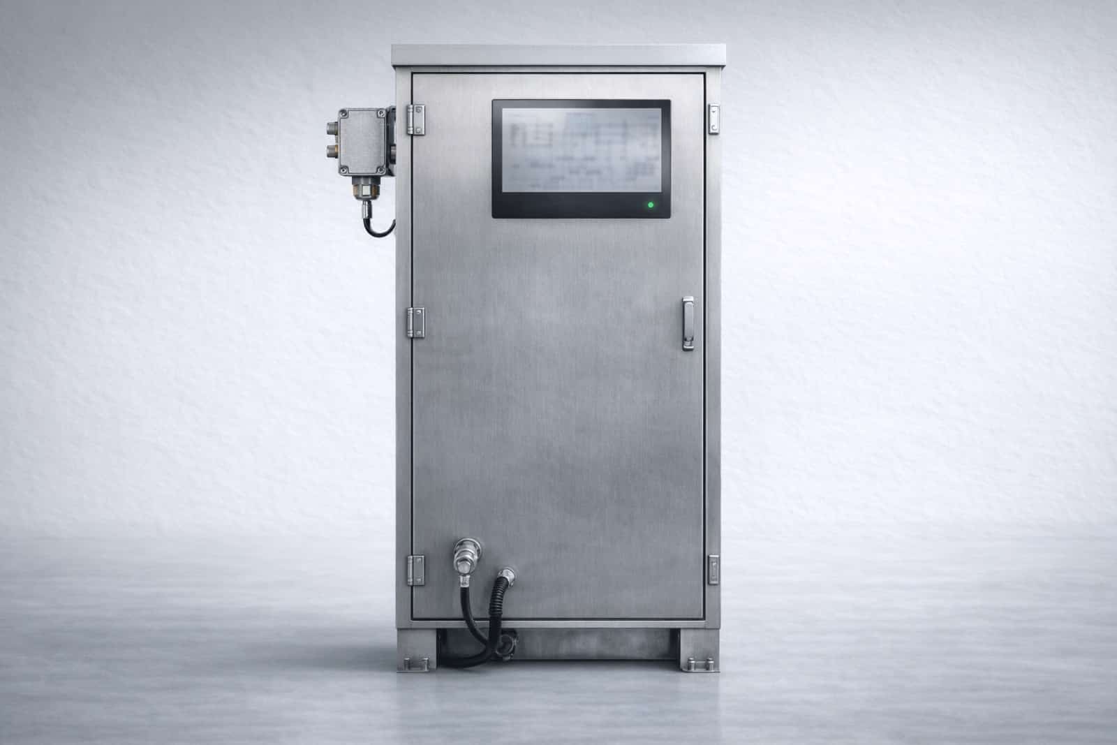
An extractive system moves gas from the process tap to an analyzer cell. This can place the instrument in an accessible cabinet, support multiple conditioning stages, and accommodate a method that specifies extraction. It also creates a longer measurement chain whose materials and temperature profile must preserve H₂S.
Review the full sample path
- Confirm the probe location represents the process stream.
- Specify wetted materials against H₂S, moisture, hydrocarbons and other corrosive or adsorptive components.
- Keep the line and conditioning stages above or below the relevant dew-point boundary as required by the method.
- Include filters, pumps, regulators, flow control, vent routing and calibration-gas connections in the response-time estimate.
- Define how the sample path will be inspected, cleaned, leak-checked and verified.
The analyzer-cell response alone is not the installed response. Transport volume, line length, flow, filters and conditioning can dominate the time between a process change and the reported value.
Information required before quotation
Primary references
Review the H₂S duty before selecting hardware
Send the measurement objective, gas matrix and installation conditions. Range, architecture, materials and certificate scope remain subject to the configured quotation.