
Updated August 2026 · Reviewed by the GESHINE technical team
CEMS analyzer components are the sample interface, conditioning system, analyzer module, PLC, DAHS, and stack parameter inputs that together make up an extractive CEMS analyzer rack — the physical cabinet that converts raw stack gas into reportable emissions data. For an extractive system — the cabinet-based architecture behind most CEMS product lines, including GESHINE’s own analyzer modules — that means six coordinated subsystems, from the probe that extracts the sample to the software that files the report.
Environmental regulations require continuous measurement rather than periodic testing, which is why every one of the six components of CEMS analyzer racks below has to keep working without a shift-change gap. Market research from Grand View Research puts hardware at 63.9% of global CEMS revenue in 2025 — most of the cost and complexity in a CEMS system sits inside the physical cabinet, not in software.
- Cabinet-based, off the stack
- Needs sample line, conditioning, DAHS
- Easier bench access for service
- Sensor mounted directly on the stack
- No sample handling or conditioning hardware
- Lower maintenance, harder analyzer access
In-situ analyzers bypass most of the anatomy below by design — they analyze inside the duct instead of extracting a sample to a cabinet. The anatomy from here on is that of the extractive, rack-based architecture that most commercial CEM systems on the market run, and it’s the sample and conditioning chain that differentiates extractive architectures.
Rack Anatomy at a Glance
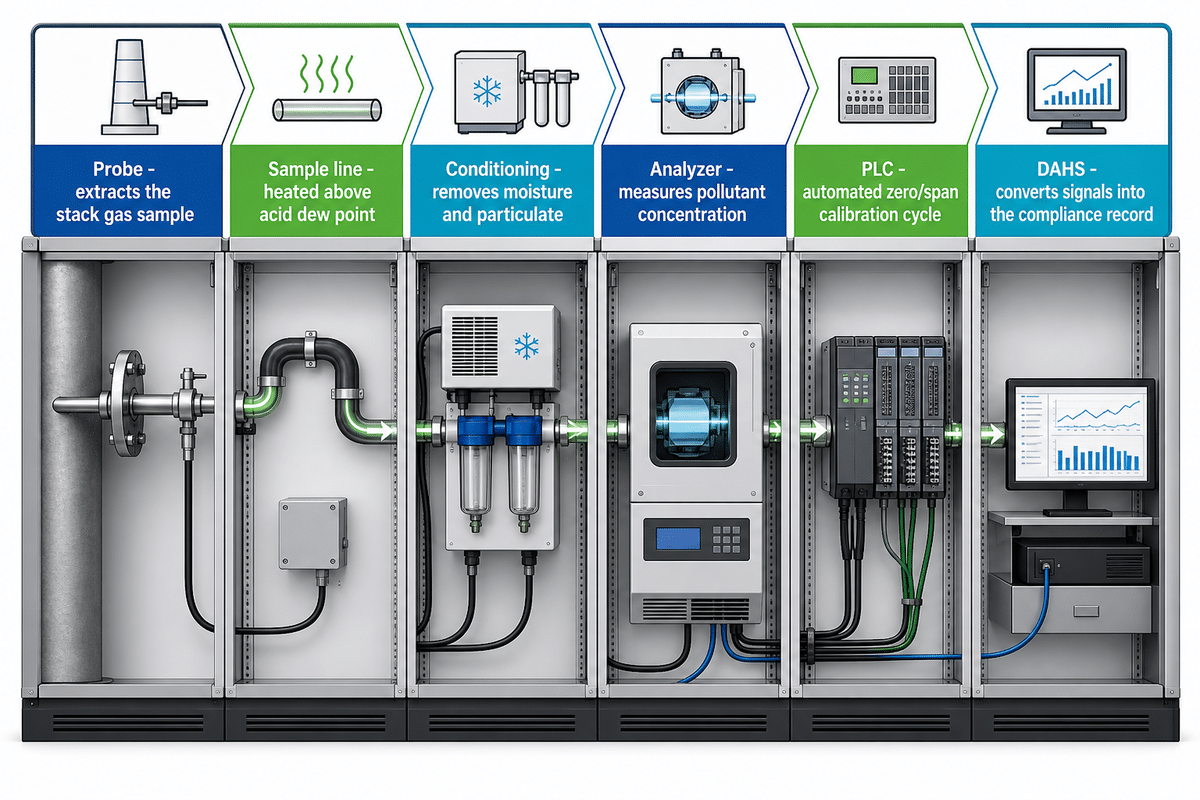
In terms of regulation, an extractive CEMS analyzer rack is one piece of equipment with multiple components. The EPA Performance Specification 2 describes it: a continuous emission monitoring system is “the total equipment required for the determination of a gas concentration or emission rate,” and specifies the sample interface, pollutant analyzer, diluent analyzer, and data recorder as major subsystems of the measurement system, the same gas components that show up in typical CEMS equipment regardless of vendor. Everything in an actual rack builds on those four categories.
Quick Specs, What’s In the Cabinet
| Sample interface | Probe, heated line, filters |
| Sample conditioning | Chiller, moisture/dust removal |
| Analyzer modules | NDIR / UV-DOAS / CLD, per pollutant |
| Control & calibration | PLC, zero/span gas system |
| Data acquisition (DAHS) | Signal-to-report computer |
| Stack parameter inputs | Flow, moisture, temp, pressure (needed to convert readings to mass-emission units) |
This CEMS analyzer components list is the inventory; the sequence below is what actually happens to a molecule of gas as it moves through each item on it.
Let’s call this the 6-Stage Rack-to-Report Framework: a molecule of stack gas moves from probe to sample line to conditioning to analyzer to PLC to DAHS, and at each step it changes form — gas, then cooled gas, then an electrical signal, then a calibrated reading, then a compliance record. A rack missing any one link or undersized at any point breaks the chain right there, not somewhere downstream. GESHINE packs five of these six subsystems — sample interface, conditioning, analyzer modules covering SO2/NOx/CO/CO2/O2, PLC and calibration, and DAHS, with stack parameter inputs offered as an option — into one turnkey cabinet, one way vendors compress the chain into fewer field connections.
That sequence is the CEMS analyzer working principle in practice — not a diagram, but literally what a probe-to-report path does gas molecule by gas molecule.
Sampling & Extraction: How Gas Gets From the Stack to the Cabinet
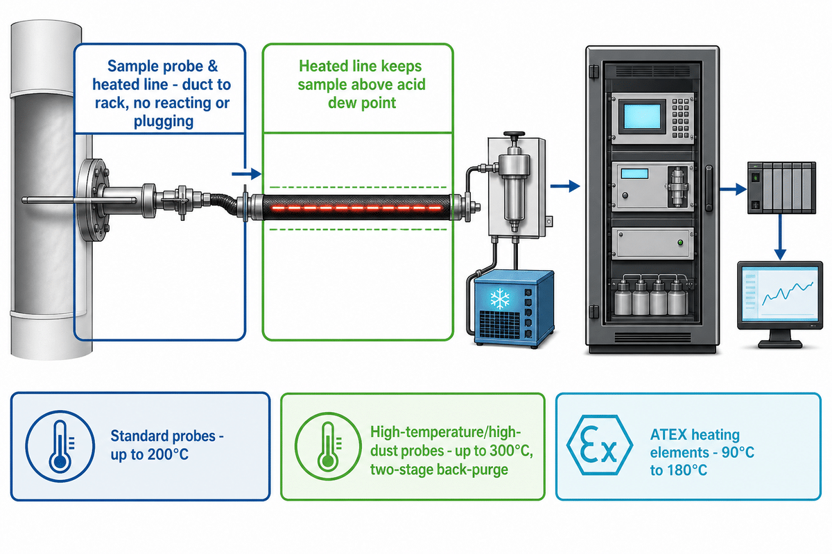
Stage one of that probe-to-report path begins at the stack: sample probe and heated line move stack gas from the duct to the rack without reacting, condensing, or plugging before it arrives. The probe is located in the stack itself, with a heated line maintaining the sample above its acid dew point on the way to the cabinet so water vapor does not drop out and wash pollutants out of the gas stream.
Probe selection is a dust- and materials-loading decision, not a catalog choice — one part of the sample interface subsystem that EPA Performance Specification 2 names as a required component of the rack. Standard heated probes generally maintain sample temperature up to 200°C, while high-temperature or high-dust models go to 300°C with two-stage back-purging; ATEX-compliant heating elements for hazardous environments operate in the 90°C to 180°C range. Field-service reports indicate a standard probe experiencing high particulate loading is often more reliably replaced with a dilution-type probe adapted to tough conditions — the solution is pairing the probe to the process, not defaulting to whatever one is on hand. If your stack is hot, wet, or dusty, that is the discussion to have with a supplier before the probe gets ordered, not after it plugs. A properly selected sampling system draws a representative gas sample on the first try rather than the third, and consistent sampling from that point forward is what protects everything downstream. This sample extraction step has one job: keep the heated sample above dew point through a stable gas flow, whatever the exhaust gas conditions are at that specific stack.
Anything downstream from the probe — the conditioning section, analyzer, DAHS — will just inherit what that inadequate probe did not quite prevent, without correction from anyone else along the chain.
Sample Conditioning: Why Raw Flue Gas Would Destroy Your Analyzers
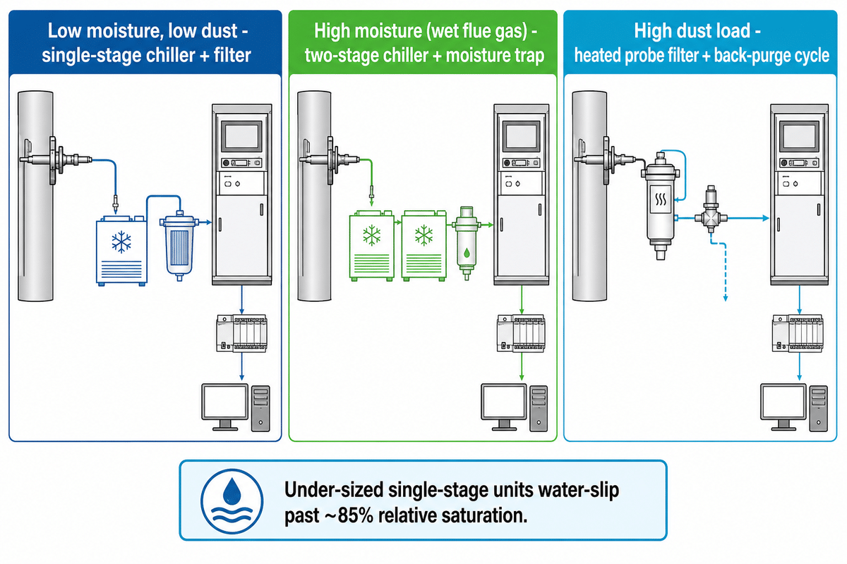
Sample conditioning — gas conditioning, in vendor spec sheets — removes moisture and particulate from the flue gas stream before it reaches the analyzer, protecting sensitive optics and cells from water slip and dust fouling, the same interference-prevention goal EPA Performance Specification 2 sets for the sample interface subsystem; the UK’s M20 quality-assurance guidance treats this stage as part of the same QAL framework as calibration.
How Do You Design a Sample Conditioning System for a CEMS?
Size the chiller and heat exchanger to the actual sample flow and moisture load at your specific site, not to the analyzer’s generic nameplate rating or a vendor’s standard spec sheet number.
| Gas condition | Conditioning approach | Limitations / Not suitable for |
|---|---|---|
| Low moisture, low dust | Single-stage chiller + filter | Not for streams above roughly 200 °C without a pre-cooler |
| High moisture (wet flue gas) | Two-stage chiller + moisture trap | Under-sized single-stage units water-slip past ~85% relative saturation |
| High dust load | Heated probe filter + back-purge cycle | Not suitable without back-purge on continuous high-PM streams |
Analyzer Modules: NDIR, UV-DOAS, CLD and Where Each One Fits
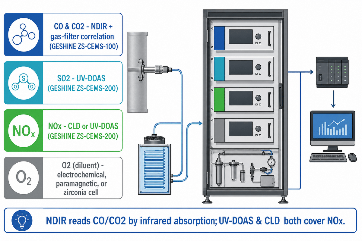
Every CEMS gas analyzer in the rack depends on the conditioning stage upstream doing its job first — no detection technology, however precise, corrects for a wet or dust-loaded sample; this is the “pollutant analyzer” and “diluent analyzer” pairing EPA Performance Specification 2 names as required subsystems.
An analyzer module performs gas measurement of pollutant concentration once the sample has been conditioned, using a technology matched to the target gas and expected concentration range. NDIR (non-dispersive infrared) reads CO and CO2 by their infrared absorption; UV-DOAS and chemiluminescence (CLD) both cover NOx, and either one, plus electrochemical or paramagnetic cells, can measure O2 — the mapping between pollutant and technology is not one-to-one, it is a shortlist you narrow by reliability under your actual process conditions. An infrared gas analyzer works by measuring how much infrared light a specific gas species absorbs, which is the underlying principle behind this class of gas detection. GESHINE’s NDIR/gas-filter-correlation channel responds in well under 1 second, fast enough to catch a transient concentration spike a slower detection technology would miss entirely.
What Gases Does a CEMS Analyzer Module Typically Measure?
Sulfur dioxide (SO2), nitrogen oxide compounds (NOx), carbon monoxide (CO), carbon dioxide (CO2), and oxygen (O2) make up the core regulated set, with HCl, HF, NH3, and moisture added depending on the source category and permit; NOx’s mixed nitrogen-oxide chemistry is why it needs a detection principle separate from carbon-based gases. GESHINE’s ZS-CEMS-100 covers CO/CO2 with NDIR and gas-filter correlation; the ZS-CEMS-200 covers SO2/NOx with UV-DOAS and CLD, two modules, two technology families, one shared cabinet architecture.
| Pollutant | Detection class | Module example |
|---|---|---|
| CO | NDIR + gas-filter correlation, <40 ms response | GESHINE ZS-CEMS-100 |
| CO2 | NDIR + gas-filter correlation | GESHINE ZS-CEMS-100 |
| SO2 | UV-DOAS | GESHINE ZS-CEMS-200 |
| NOx | CLD or UV-DOAS | GESHINE ZS-CEMS-200 |
| O2 (diluent) | Electrochemical, paramagnetic, or zirconia cell | Industry-standard diluent monitor |
| HCl / HF | FTIR or TDLAS | Specialty acid-gas module |
| NH3 | TDLAS | Specialty ammonia-slip module |
| Moisture (H2O) | TDLAS or condensation-based | Stack parameter subsystem |
| Multi-gas (SO2/NOx/CO/CO2/O2) | Combined technologies, one cabinet | GESHINE ZS-CEMS-300 |
A practitioner working CEMS calibration puts it plainly: “The right technology is not always the most advanced one. It is the one that provides reliable measurement for the process conditions you have.” A newer measurement principle that is fussier about your gas’s temperature or dust load is not an upgrade.
CEMS analyzer manufacturers do not all split these six subsystems the same way — GESHINE bundles five of six into one ZS-CEMS-300 cabinet, while other vendors sell sampling, conditioning, and analysis as separate line items you integrate yourself.
PLC Control & Automatic Calibration: Keeping the Rack Honest
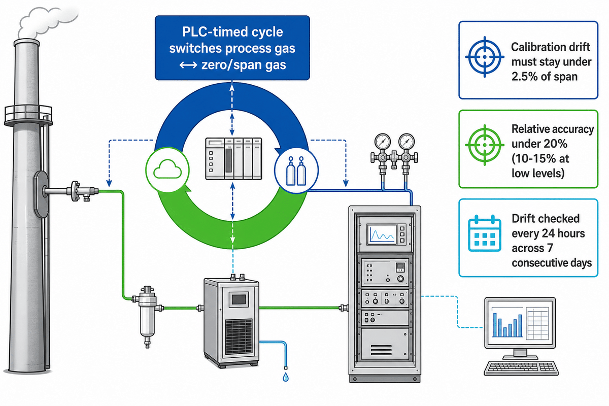
Process control and process monitoring both depend on the same automated cycle — monitoring gas concentration continuously is what lets the PLC catch drift before it becomes a compliance problem. At the center of the cabinet is the automated, PLC-timed cycle that switches the sample line back and forth between process gas and zero gas or span calibration gas so the analyzer’s reading against a known reference can be checked. For SO2/NOx CEMS specifically, EPA Performance Specification 2 sets that acceptance bar in exact numbers: calibration drift must not exceed 2.5 percent of the span value, and relative accuracy must stay under 20 percent, dropping to 10-15 percent at lower emission levels. Those thresholds are specific to SO2/NOx acceptance testing; other pollutants are covered by their own separate EPA performance specifications, but they are a concrete example of what “in calibration” actually means in regulatory terms, not a vague target.
Automatic calibration runs on a schedule — EPA’s own calibration-drift test procedure checks drift at 24-hour intervals across 7 consecutive days at initial certification — cycling reference gas through the same path the sample gas travels so drift in the sample lines gets caught along with drift in the analyzer itself. A rack that skips this step, or runs it manually and irregularly, is the one most likely to fail a relative-accuracy audit months after installation — not because the analyzer degraded, but because nobody was watching it happen.
Data Acquisition & Handling System (DAHS): From Raw Signal to Reportable Data
What Is a Data Acquisition and Handling System (DAHS)?
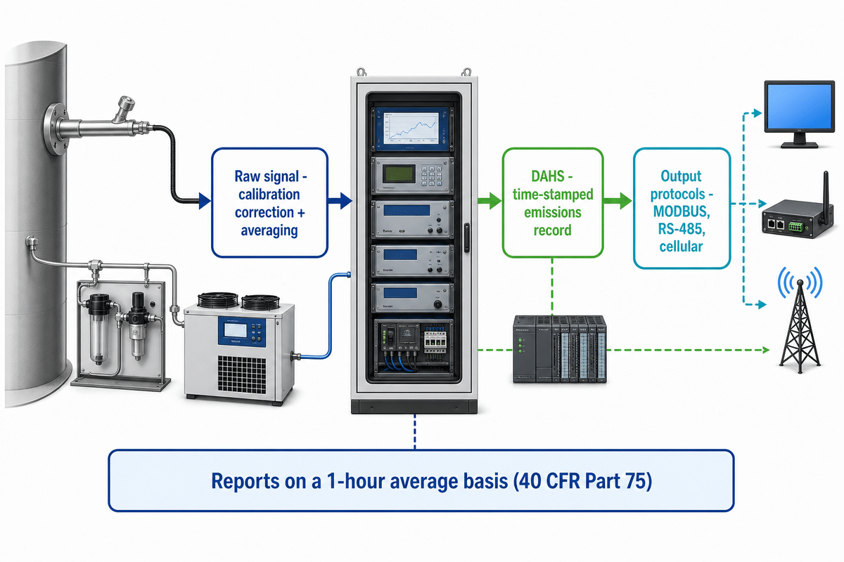
The DAHS is the computer that converts analyzer signals into the calculated, time-stamped emissions record a regulator will accept.
DAHS responsibilities extend past collecting and formatting numbers. Under 40 CFR Part 75, specified monitoring-system or process changes, replacing an analyzer, relocating a sample probe, can trigger recertification, and substitute-data rules apply to fill the reporting gap until the required tests are completed successfully. Failing to flag when a component change has invalidated its own data stream turns a DAHS into a compliance liability, not just a data-logging shortfall. Under Part 75, the DAHS calculates and reports pollutant concentrations on a 1-hour average basis, so even a short outage matters. GESHINE’s ZS-CEMS-300 pairs its multi-gas analyzer set with an integrated data-logging function as part of the same cabinet, rather than treating the DAHS as a separate add-on system. Environmental monitoring at the rack level runs through that same DAHS, and compliance with environmental regulation depends on data acquisition systems that never miss a reporting interval.
Compliance Requirements: What Regulators Actually Require of These Components
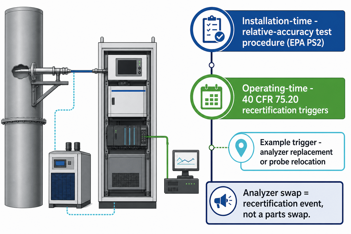
Continuous monitoring compliance splits into two component-level questions: does the hardware meet an installation-time performance spec, and does it stay certified through operating-time changes? EPA Performance Specification 2 answers the first question for SO2/NOx systems with a defined relative-accuracy test procedure at installation. That second question is governed by 40 CFR 75.20, which lists the specific triggers for recertification.
If you want the full underlying language rather than a summary, EPA’s own CEMS analyzer components PDF — Performance Specification 2 — spells out the sample interface, pollutant analyzer, diluent analyzer, and data-recorder requirements in the regulator’s exact wording.
“Examples of changes which require recertification include: replacement of the analyzer; change in location or orientation of the sampling probe or site…”
40 CFR 75, Subpart C (Operation and Maintenance Requirements), eCFR current edition
That clause matters at purchase time, not just during operation: swapping an analyzer module later is a recertification event, not a parts swap. Buyers outside the US should not assume the EPA framework transfers directly; the European equivalent, EN 14181, runs its own QAL1/QAL2/QAL3 quality-assurance levels and allows an already-installed system with a non-ideal certified range to keep operating if it satisfies those QAL and surveillance-test requirements.
Verification Checklist Before You Sign Off on a CEMS Rack
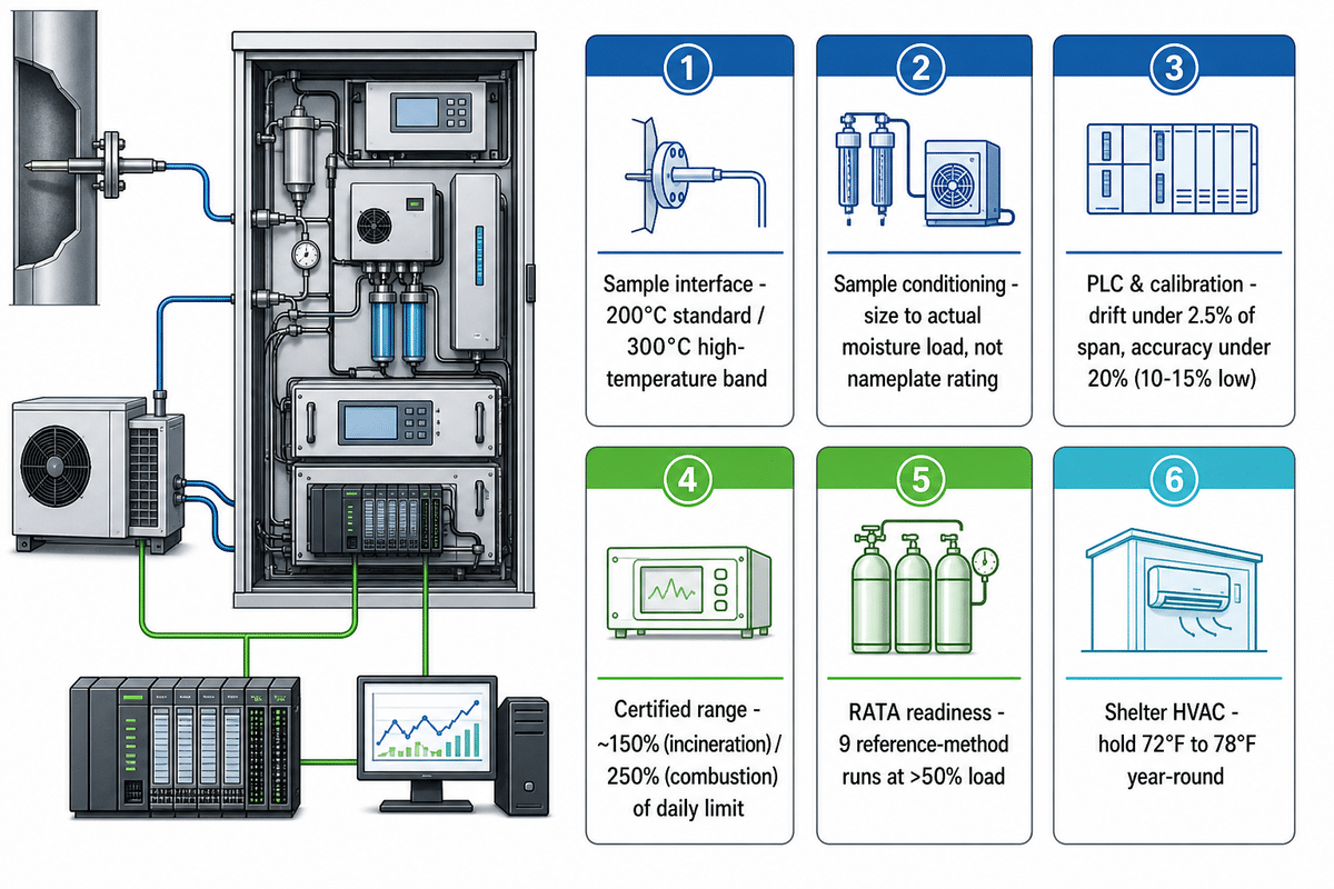
Before a CEMS rack purchase order gets approved, the buyer’s job is to verify the vendor’s claims against the same regulatory language a testing auditor will use later — not to re-litigate the vendor’s marketing copy. The CEMS Rack Verification Checklist below is what that verification actually looks like in practice.
- Confirm the certified measurement range against your permit’s daily emission limit before ordering
- Ask for the DAHS communication protocol in writing (MODBUS/RS-485/cellular) before committing to your DCS integration
- Request the exact recertification triggers your specific monitoring plan falls under
- Verify sample conditioning capacity against your actual moisture and dust load, not a generic spec sheet number
- Assume a wider certified range is automatically the safer choice — regulators evaluate range against your permit’s daily limit, not against a safety margin you picked yourself
- Take a vendor’s compliance claim at face value without the underlying performance-specification test data
- Treat an in-situ quote and an extractive quote as interchangeable line items
- Skip asking who performs recertification testing after an analyzer swap, or how long that takes
Most counterintuitive on that list is the range question, because it inverts the usual “buy more margin” instinct: one CEMS vendor’s own selection guidance states that a certified measurement range should stay within roughly 150% of the daily emission limit for incineration sources and 250% for combustion sources — go wider than that at the selection stage and you can find yourself outside the range a testing auditor will accept, not more protected. Already-installed systems get more flexibility on this under frameworks like EN 14181, but a new purchase decision does not.
| Verification point | What to confirm before sign-off | Regulatory or technical basis |
|---|---|---|
| Sample interface | Heated line holds the sample above its acid dew point across your specified probe temperature band (standard to 200°C, high-temperature to 300°C) | Prevents water slip before gas reaches conditioning |
| Sample conditioning | Chiller and heat exchanger sized to actual site moisture load, not a generic nameplate rating | Under-sized conditioning is one of the most commonly documented CEMS field failures |
| Analyzer modules | Detection technology (NDIR, UV-DOAS, or CLD) matched to the specific pollutant and concentration range | Wrong technology choice degrades reliability under real process conditions |
| PLC and calibration | Calibration drift confirmed under 2.5% of span, relative accuracy under 20% (10-15% at low emission levels) | EPA Performance Specification 2 acceptance criteria for SO2/NOx |
| DAHS | Communication protocol (MODBUS, RS-485, or cellular) confirmed in writing before DCS integration begins | A mismatched protocol turns a data logger into an integration project |
| Recertification triggers | Exact list of monitoring-system changes that trigger recertification obtained in writing | 40 CFR 75.20 lists specific triggers, not a general industry rule |
| Certified range | Range stays within roughly 150% of the daily limit for incineration sources or 250% for combustion sources | Going wider risks falling outside what a testing auditor accepts |
| RATA readiness | Vendor can support a minimum of nine reference-method test runs at more than 50% load | EPA Performance Specification 2 RATA procedure requirement |
| Shelter and HVAC | Heating and cooling sized to hold roughly 72°F to 78°F year-round at your specific site | Undersized HVAC shows up as calibration drift, not an obvious defect |
Integration & Utility Requirements: Power, Gas Supply and Footprint
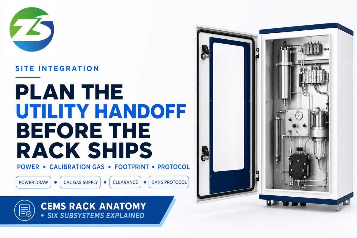
A CEMS rack needs more from your facility than a mounting bracket. Before installation, confirm available power draw, calibration gas supply logistics, cabinet footprint, and — if the rack will report to an existing control system — PLC or DAHS protocol compatibility, the same handoff 40 CFR 75.20 assumes is already in place when it sets recertification triggers. Installation guidance from equipment suppliers consistently treats site selection and space allocation as a distinct planning step, separate from ordering the hardware itself: the sampling probe location has to sit where the gas is representative and undisturbed, and the cabinet needs enough clearance for routine maintenance and calibration access, not just enough floor space to set the box down.
A CEMS system in power plant service runs through continuous 24/7 stack conditions that push every one of these six stages harder than a lab bench test ever would, which is part of why the point below on shelter conditioning matters more here than on an intermittent source.
This is also where a rack that looked correctly specified on paper fails in the field: shelter HVAC undersized for the local climate shows up as calibration drift that tracks outdoor temperature swings, not as an obvious installation defect. Field-service guidance targets a stable shelter range of roughly 72°F to 78°F year-round; confirm heating and cooling capacity for your site’s actual seasonal range before the rack ships, not after the first hard freeze or heat wave exposes the gap.
RATA Testing & Verification: Proving the Rack Measures What It Claims
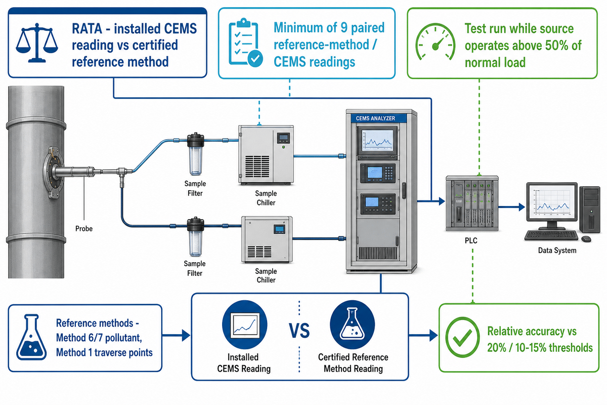
A Relative Accuracy Test Audit (RATA) is the periodic field test that compares the installed CEMS reading against a certified reference method, confirming the rack still measures within the tolerance it was certified to at installation. EPA Performance Specification 2 sets the general test structure: a minimum of nine sets of paired reference-method and CEMS readings, run while the source operates above 50% of normal load, with the resulting relative accuracy calculated against the same 20%/10-15% thresholds used at initial certification. Exact reference-method sampling details — traverse-point count and location, minimum run duration — are set by the specific EPA reference method the RATA firm applies (for example, Method 6 or 7 for the pollutant, Method 1 for traverse-point selection), not by Performance Specification 2 itself, which is one more reason to confirm the test protocol with your RATA vendor in writing rather than assume a single fixed procedure.
RATA failures rarely trace back to the analyzer alone. Field-service reviews of common CEMS failure modes list plugged probe filters, corrosion in sample lines, and dirty gas coolers as recurring root causes that surface first as a failed accuracy test, not as an obvious hardware fault — which is why the verification checklist earlier in this guide asks about maintenance access and spare-parts lead time, not just initial specifications. Ask your vendor how RATA support is structured before you need it, not after a test fails.
Frequently Asked Questions
Q: What is a CEMS analyzer?
A CEMS analyzer is the measurement module inside a continuous emission monitoring system that senses pollutant concentration in the gas stream and outputs a calibrated signal proportional to it.
Q: What are the components of a CEMS analyzer rack?
Six coordinated subsystems make up a complete rack: sample probe/extraction, conditioning, analyzer modules, PLC control and calibration, the DAHS, and stack parameter monitoring for accurate mass-emission conversion.
Q: How much does a CEMS analyzer cost?
Costs vary widely by component, technology, vendor region, and whether you’re buying individual parts or a turnkey cabinet, since no single published price band covers every configuration.
Q: Which facilities are required to install a CEMS?
Facilities subject to specific EPA source-category rules under 40 CFR Part 60 or Part 75, power generation, large industrial boilers, and other regulated combustion or process sources.
Q: What happens if pollutant emissions exceed the permit limit?
DAHS software automatically logs and flags the exceedance, and the facility must report it to the regulator per its monitoring plan and applicable permit conditions.
Q: What are common issues that require CEMS analyzer maintenance?
Plugged probe filters, moisture bypassing the conditioning system, corrosion from acidic condensate, dirty instrument air, and improper shelter HVAC are the most frequently documented root causes.
Q: Why does a CEMS need both a sample conditioning system and a calibration system?
Conditioning protects the analyzer hardware from the raw gas it’s measuring; calibration separately confirms the analyzer is still reading that protected, conditioned gas sample correctly over time.
Why We Write This
GESHINE builds the ZS-CEMS analyzer modules referenced in this guide, so the component breakdown above is grounded in what we manufacture, NDIR, UV-DOAS, and CLD gas analysis, turnkey multi-gas cabinets, and the sample conditioning and data logging that go with them. We wrote this as a scoping and verification reference for engineers comparing rack architectures, not as a product pitch, which is why the compliance figures here are cited from EPA and eCFR, not a vendor summary.
References & Sources
- EPA Performance Specification 2 — Specifications and Test Procedures for SO2 and NOx CEMS U.S. Environmental Protection Agency
- 40 CFR 75.20, Initial certification and recertification procedures eCFR, U.S. Government
- 40 CFR Part 75, Subpart C, Operation and Maintenance Requirements eCFR, U.S. Government
- M20: Quality Assurance of Continuous Emission Monitoring Systems (EN 14181 guidance) UK Environment Agency
Related Articles
Reviewed by the GESHINE technical team. Updated August 2026.